Inkjet printing apparatus and inkjet printing method
a printing apparatus and inkjet technology, applied in the field of inkjet printing apparatus and inkjet printing method, can solve the problems of reducing printing density, reducing lines, and reducing lines, and reducing printing density, so as to reduce printing density, reduce ink droplets, and increase the discharge amount of ink droplets
- Summary
- Abstract
- Description
- Claims
- Application Information
AI Technical Summary
Benefits of technology
Problems solved by technology
Method used
Image
Examples
first embodiment
[0025] Embodiments of a printing apparatus according to the present invention will be described with reference to the drawings. Incidentally, they will be described by taking as an example an inkjet printing apparatus capable of printing color images using an inkjet printing scheme.
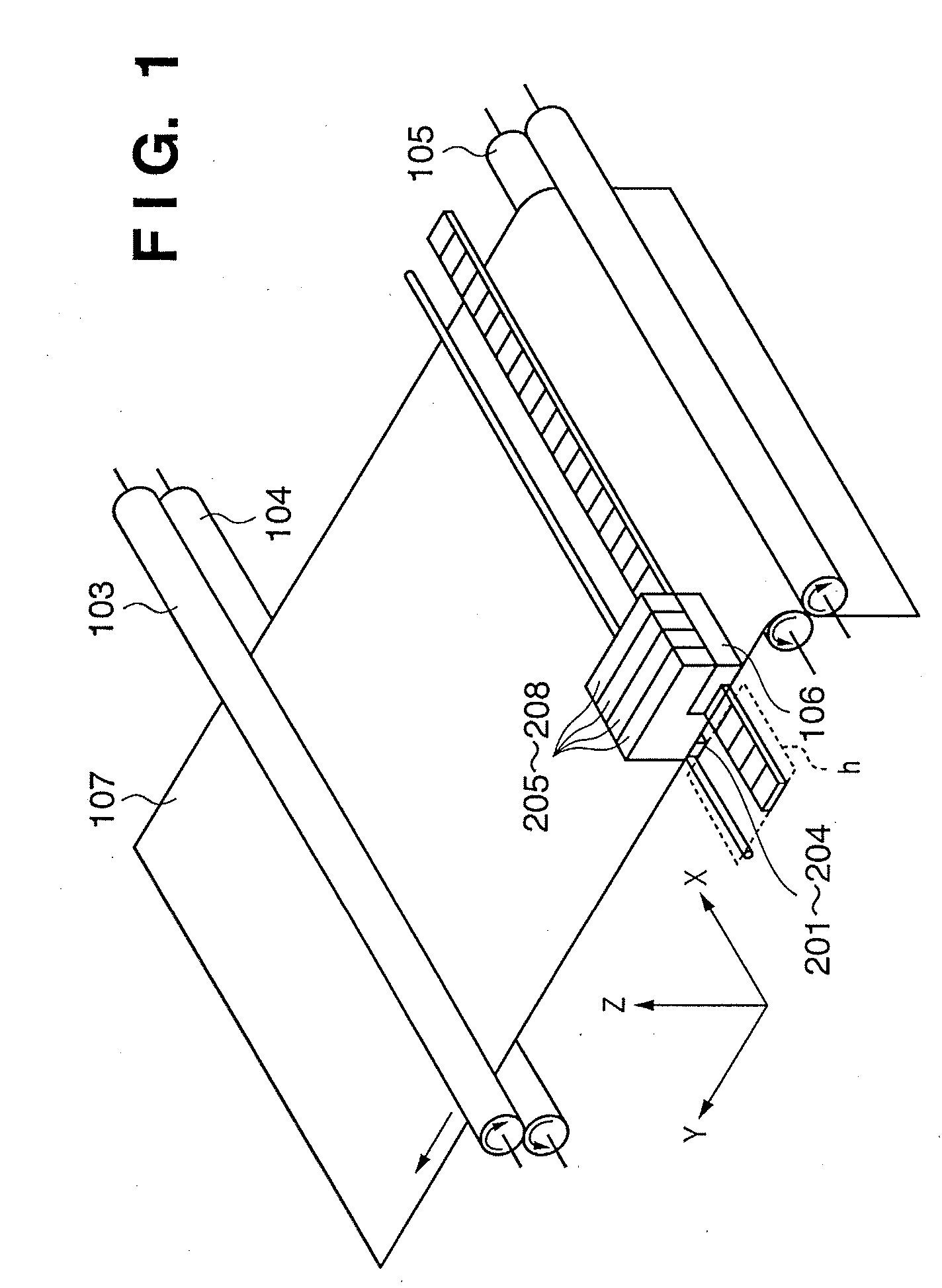
[0026]FIG. 1 is a schematic perspective view showing the configuration of an embodiment of an inkjet printing apparatus to which the present invention can be applied. In FIG. 1, reference numerals 205 to 208 denote ink cartridges. Ink cartridges 205 to 208 include ink tanks containing four color inks (black, cyan, magenta, and yellow: Bk, C, M, and Y), respectively, and four printheads 201 to 204 corresponding to the four color inks.
[0027] Reference numeral 103 denotes a paper feed / drive roller, which rotates in the direction of the arrow in the figure while holding down recording medium 107 in conjunction with an auxiliary roller 104, and thereby conveys the recording medium 107. Furthermore, the paper...
second embodiment
[0053] A second embodiment of the present invention makes it possible to print high-density, high-quality characters and line drawings while maintaining better definition by performing two or more scans for printing with each printhead to increase the duty factor for printing of the non-edge portion over the duty factor for printing of the edge portion.
[0054]FIG. 9 is an overall functional block diagram showing data processing according to the second embodiment. FIG. 10 is a flowchart illustrating the second embodiment. Edge data 2001 and non-edge data 2005 are generated through an edge and non-edge detecting process 2000 (Step S201).
[0055] In an odd scan for printing (Step S202), the edge data is subjected to a first edge reducing process (Step S203) by a first edge reducing mask 2002 to generate edge reduced data 2004. On the other hand, the non-edge data is subjected to a first non-edge reducing process (Step S204) by a first non-edge reducing mask 2006 to generate non-edge red...
third embodiment
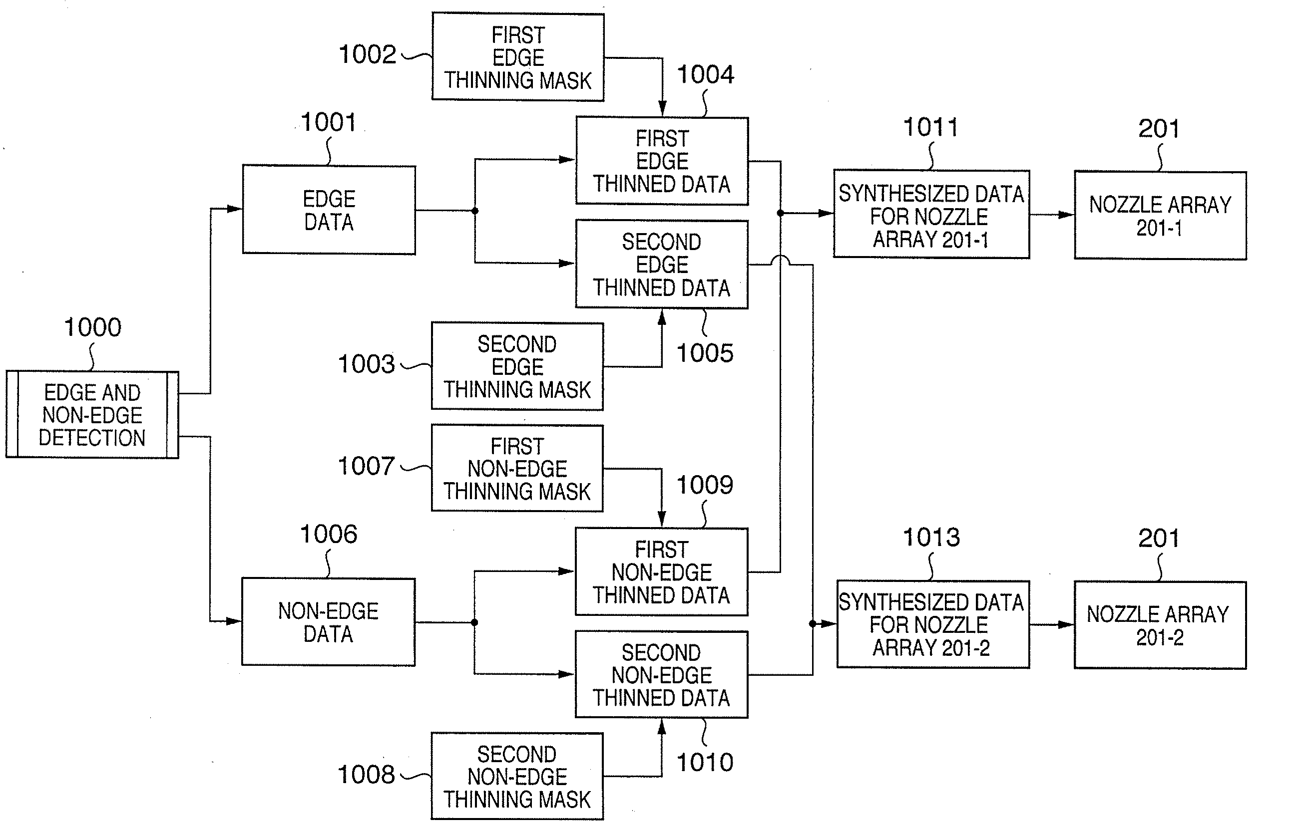
[0058] A third embodiment of the present invention relates to a method for printing edge portions with a single nozzle array 201-1, and non-edge portions with two nozzle arrays 201-1 and 201-2 of the printhead 201 to reduce degradation of character quality due to misalignment of the printheads.
[0059]FIGS. 11A to 11H are diagrams illustrating the operation of edge and non-edge reducing processes according to the third embodiment of the present invention. The non-edge data in FIG. 11A is ORed with the first non-edge mask of a 75% duty factor to generate the first non-edge reduced data in FIG. 11B. It is assumed here that the first non-edge mask is composed of a 2×2 matrix and that the pixels in the non-edge data are ORed with it repeatedly in units of 2×2 pixels.
[0060] Similarly, the non-edge data is ORed with the second non-edge mask of a 75% duty factor to generate the second non-edge data in FIG. 11C. Dots are generated in the first non-edge data and second non-edge data which co...
PUM
 Abstract
Description
Claims
Application Information
 - R&D
- Intellectual Property
- Life Sciences
- Materials
- Tech Scout
- Unparalleled Data Quality
- Higher Quality Content
- 60% Fewer Hallucinations
Browse by: Latest US Patents, China's latest patents, Technical Efficacy Thesaurus, Application Domain, Technology Topic, Popular Technical Reports.
© 2025 PatSnap. All rights reserved.Legal|Privacy policy|Modern Slavery Act Transparency Statement|Sitemap|About US| Contact US: help@patsnap.com


