
Electronic kitchen dispensing faucet

a technology of electronic kitchen and faucet, which is applied in the direction of liquid transferring device, process and machine control, instruments, etc., can solve the problems of insufficient control of temperature accuracy, inconvenient placement of known liquid-dispensing devices within smaller kitchens, and insufficient accuracy of devices for small volumes that are desired in many kitchens. , to achieve the effect of increasing or decreasing the flow rate, increasing or decreasing the flow resistance, and increasing the flow ra

Inactive Publication Date: 2007-07-05
EDGEWATER FAUCET
View PDF13 Cites 55 Cited by
  • Summary
  • Abstract
  • Description
  • Claims
  • Application Information

AI Technical Summary

Benefits of technology

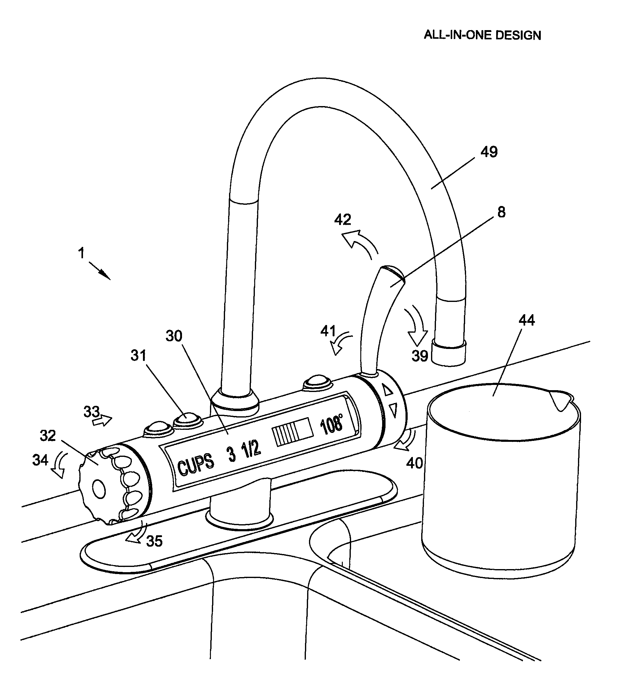
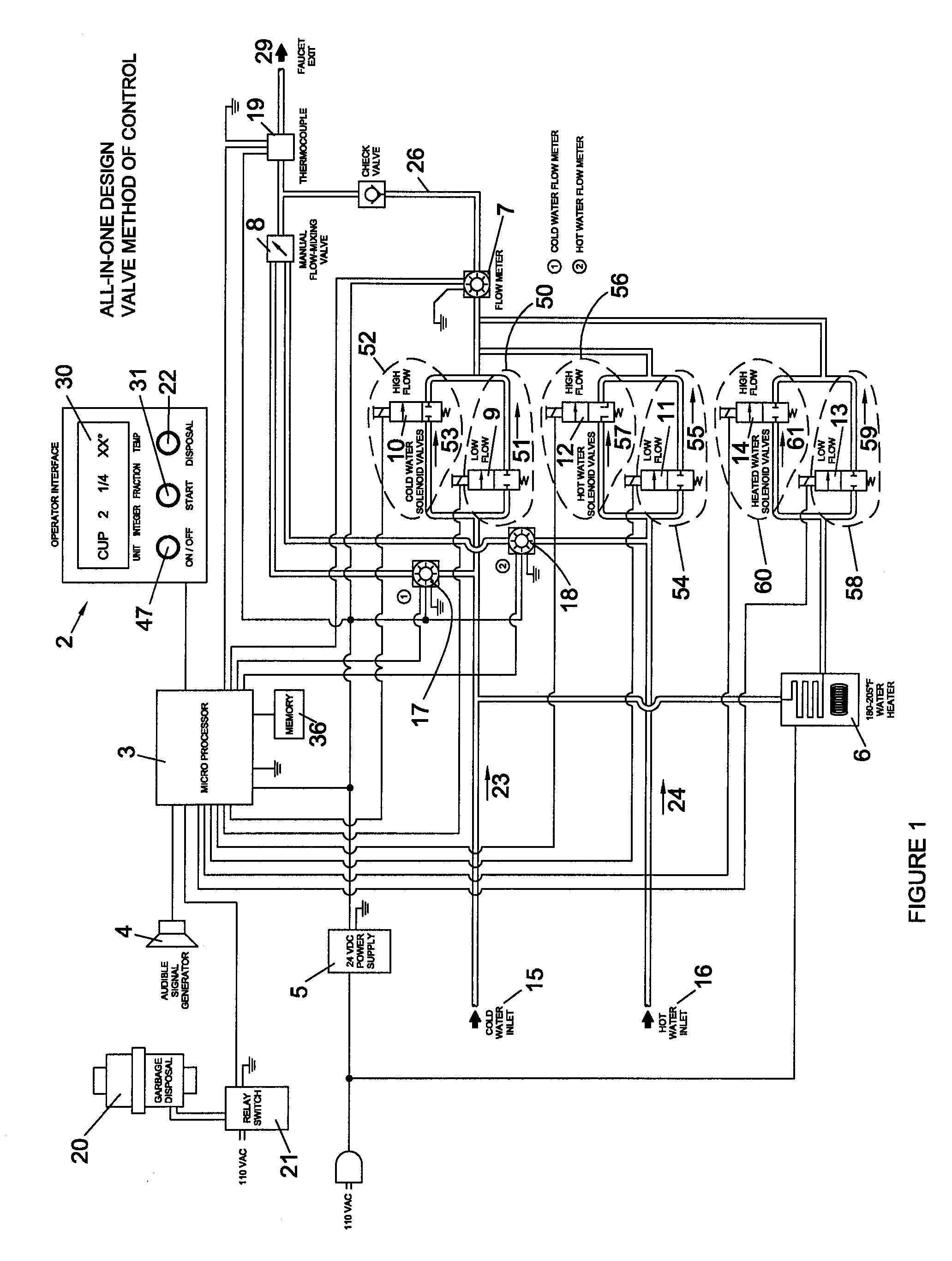
[0017] In another aspect of the present invention, a kitchen faucet apparatus adapted to dispense a selected amount of liquid includes a base, a faucet supported on the base, a first circuit having a first flow rate and adapted to connection to a source of liquid, and a second circuit having a second flow rate and adapted to connection to a source of liquid. The first and second circuits are connected to the faucet and include valves for controlling the first and second flow rates to accurately deliver a total flow amount of as little as ½ teaspoon and as great as at least 1 gallon. A controller is programmed to variably control the flow-controlling devices of the first and second circuits to output a selected quantity of liquid.
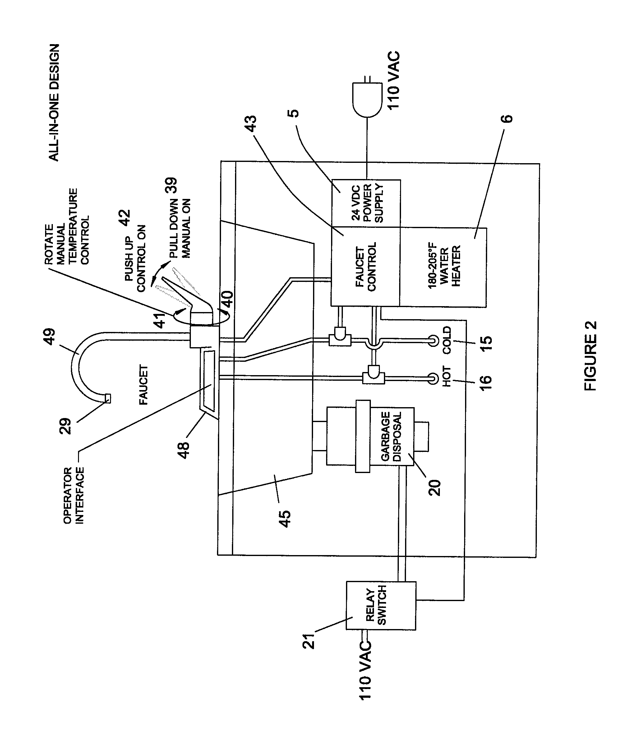
[0033] Another aspect of this device is a control device attached to a kitchen sink garbage disposal. The control device provides a signal for activating the garbage disposal only when the liquid flow sensor detects a sufficient volume of water flowing through the faucet. The garbage disposal would turn off when the flow of water through the faucet is interrupted; thereby preventing damage to the garbage disposal.

Problems solved by technology

However, these devices are not sufficiently accurate for small volumes that are desired in many kitchens, nor are they sufficiently controlled for accurate temperatures as needed in many kitchens, especially consumer kitchens where recipes are relatively small.
Further, known liquid-dispensing devices are not configured to be conveniently located within smaller kitchens and do allow for dispensing precise volumes of liquid, or more specifically water, into a container for reconstituting pre-packaged food or mixing with other recipe ingredients.
Still further, known systems are not configured to automatically adjust the flow rate of liquid based on the volume of liquid to be dispensed.
Still further, known liquid-dispensing devices cannot accurately dispense a precise volume of liquid at specific temperatures.
If the liquid is too hot, the yeast is instantly killed.
If the liquid is too cool, the yeast will cake or not produce sufficient quantities of carbon dioxide for proper rising.
Should the kitchen faucet not have sufficient liquid flowing, the garbage disposal unit would not operate, even when requested by the operator.
While some manufacturers have attempted to solve the dispensing of specific volumes of liquid for industrial baking or processing, known devices are typically too big and cumbersome to be retrofitted to a commercial or consumer kitchen sink.
While this device may be useful for dispensing a large volume of liquid for batch processing, it is inadequate for dispensing small volumes of liquid and / or for dispensing precise volumes of liquid, which items are needed in preparing recipes in the commercial or consumer kitchen.
This spillage compensation method would not work for kitchen recipes or food preparation.
If used in preparing cooking recipes or other food preparation, the results would be disastrous as the outcome of the recipe would be compromised by the spillage of the liquid and the ensuing mixture.

Method used


Image

  • Electronic kitchen dispensing faucet
  • Electronic kitchen dispensing faucet
  • Electronic kitchen dispensing faucet

Examples


first modification

[0132] The apparatus 1A (FIG. 12) for an All-in-One electronic dispensing kitchen faucet includes a base 48, a spout 49, a first circuit 50A, a first positive-displacement pump 10A, and a programmable controller 3. The base 48 is adapted for mounting to a kitchen sink 45. The spout 49 extends from the base 48 for dispensing the total amount of liquid. The first circuit is adapted for connection to a first source of liquid 15 to dispense liquid from the first source through the first circuit 50A.

[0133] The first positive-displacement pump 10A (FIG. 12) is connected to a first motor 9A. The first positive-displacement pump 10A generates a specific volume output for a given input. By activating the first positive-displacement pump 10A with the first motor 9A for a controlled number of rotations, it will accurately dispense a measured amount of first source liquid flowing through the faucet exit 29. Those skilled in the art will understand that a pump can be driven in different manners...

second modification

[0174] The apparatus 1B (FIG. 17) for an All-in-One electronic dispensing kitchen faucet includes a base 48, a spout 49, a first circuit 50B, a first flow meter 10B, a first flow-restrictor apparatus 9, and a programmable controller 3. The base 48 is adapted for mounting to a kitchen sink 45. The spout 49 extends from the base 48 for dispensing the total amount of liquid. The first circuit being adapted for connection to a first pressurized source of liquid 15 to dispense liquid from the first source through the first circuit 50B.

[0175] The first flow meter 10B (FIG. 17) is connected to a first flow-restrictor apparatus 9B. The first flow meter 10B generates a first signal as a specific volume of liquid flows through the flow meter. By summing the signals generated by the flow meter 10B, the total volume flowing through circuit 50B and the faucet exit 29 may be calculated. After the Operator specified quantity of liquid is dispensed from the faucet exit, the first flow-restrictor a...


PUM


Abstract

An electronic kitchen faucet dispensing apparatus capable of dispensing measured operator-selectable quantities of hot or cold liquid into a container with a flow rate suitable to prevent splashing and loss of the ensuing mixture while maintaining a rapid flow rate to quickly fill larger containers. The dispensing faucet can be used for measuring liquids required for preparing recipes, making instant beverages, or in the preparation of pre-packaged foods, and may be retrofitted to an existing faucet. The apparatus may utilize various controls to automatically control liquid flow, including 1) flow sensors and control valving; 2) positive-displacement pumps; and 3) flow-restrictors with shut-off valves. Also, it can be connected to a garbage disposal to prevent damage to the disposal.

Description

CROSS REFERENCE TO RELATED APPLICATION [0001] This application is a continuation-in-part of application Ser. No. 11 / 023,740, filed Dec. 28, 2004, entitled ELECTRONIC KITCHEN DISPENSING FAUCET. This application also claims benefit of provisional application Ser. No. 60 / 782,335, filed Mar. 14, 2006, entitled ELECTRONIC KITCHEN DISPENSING FAUCET, and also claims benefit of provisional application Ser. No. 60 / 791,352, filed Apr. 12, 2006, entitled ELECTRONIC KITCHEN DISPENSING FAUCET. The entire content of each of the above applications is incorporated herein by reference in their entirety.BACKGROUND OF THE INVENTION [0002] The present invention relates to liquid measuring and dispensing devices, and more particularly relates to devices for accurate and easy dispensing of adjustable amounts of liquid and / or at adjustable desired temperatures. [0003] Liquid measuring and dispensing devices exist for use in industrial applications and beverage dispensing devices. An industrial dispenser i...

Claims


Application Information

Patent Timeline
Patent Type & Authority Applications(United States)
IPC IPC(8): G05D23/13B67D5/08B67D5/16B67D7/08B67D7/16
CPCE03C1/055G05D23/1393E03C1/266
Inventor STOWE, ELLIOTT V.BLAKE, RICHARD R.GRAY, PAUL J.NEWHOUSE, THOMAS J.BERGERON, MICHAEL A.
Owner EDGEWATER FAUCET
Learn More