
Susceptor

a technology of suceptor and spherical tube, which is applied in the direction of chemical vapor deposition coating, electric discharge tube, coating, etc., can solve the problems of reducing the degree of vacuum inside the chamber, reducing the yield of the resulting products, and generating particles, so as to suppress the generation of particles, suppress the abnormal leakage of gas, and suppress the effect of extensive gas leakag

Active Publication Date: 2007-06-28
KYOCERA CORP
View PDF9 Cites 170 Cited by
  • Summary
  • Abstract
  • Description
  • Claims
  • Application Information

AI Technical Summary

Benefits of technology

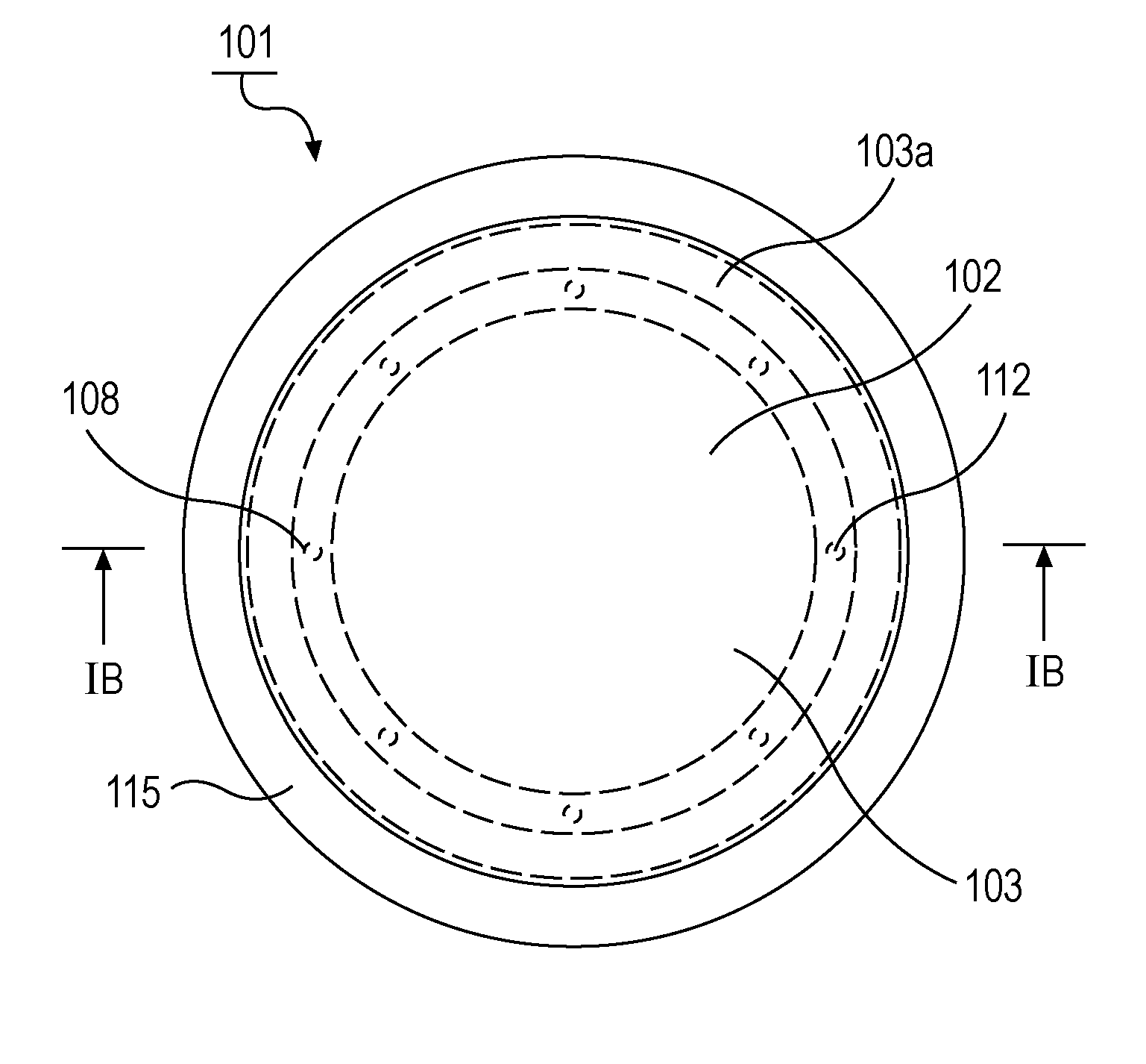
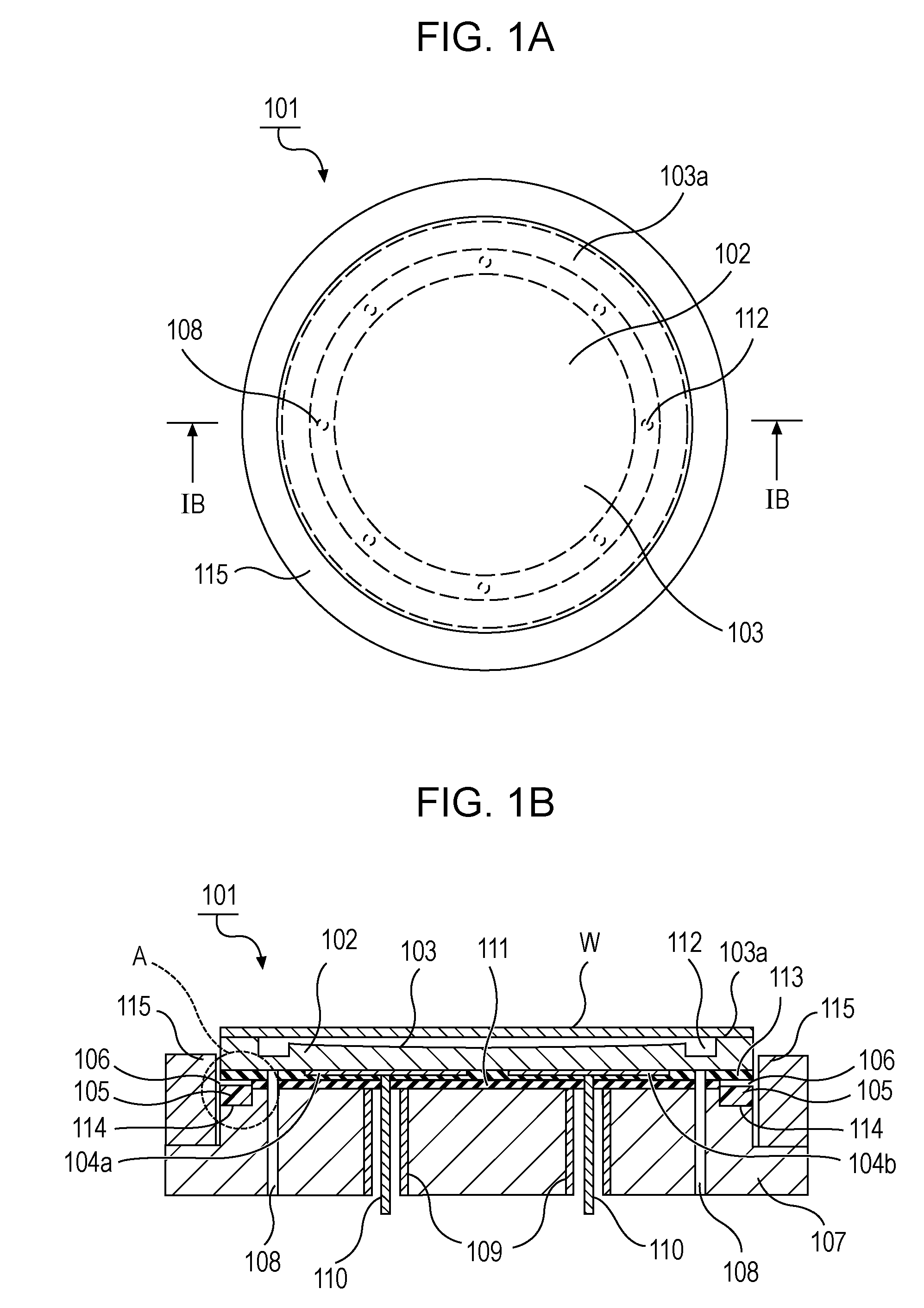
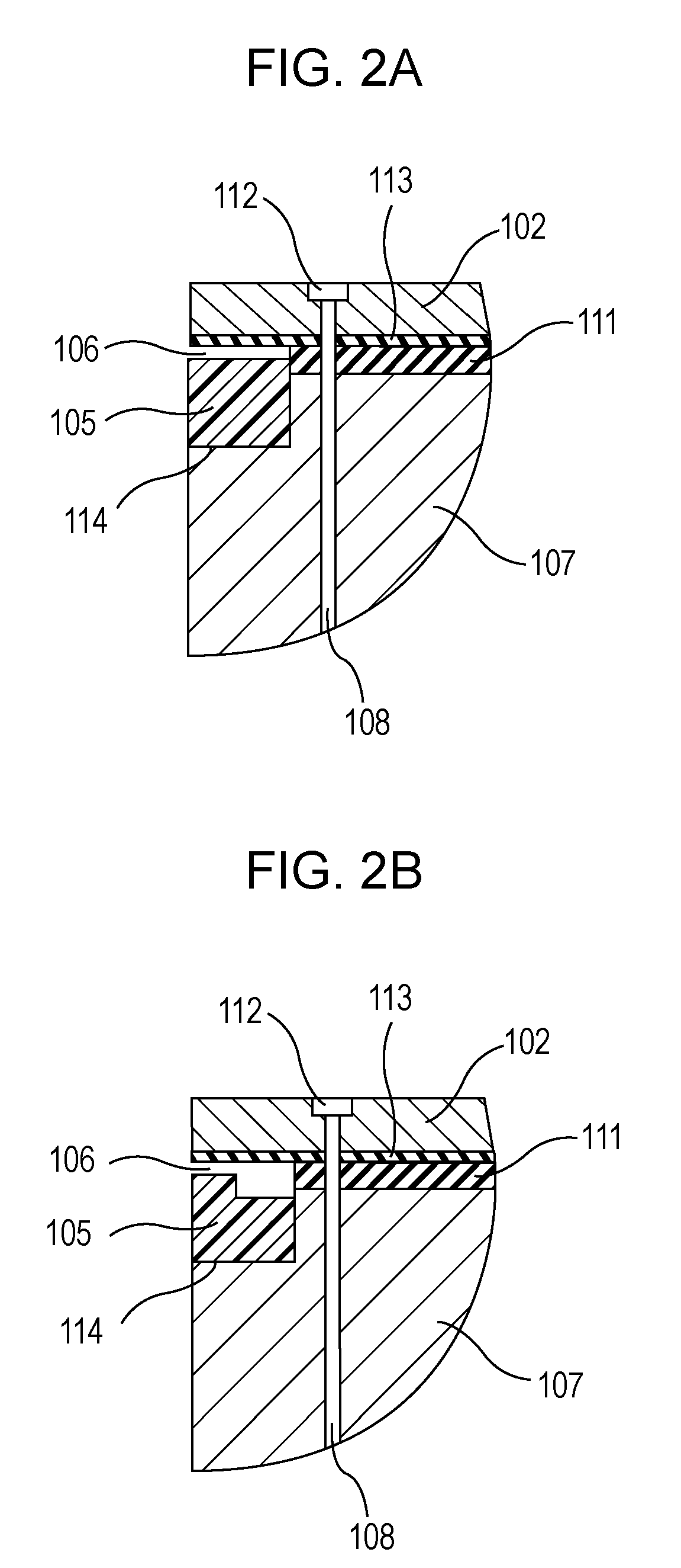
[0010] The present invention has been made to overcome the problems described above and aims to provide a susceptor that can inhibit generation of particles resulting from plasma corrosion of a bonding layer between a base member and a plate member, that can suppress extensive leakage of gas from the space between the plate member and a substrate in an amount larger than the set value, and that can suppress abnormal leakage of gas from any gap between the plate member and the substrate.
[0011] The present invention provides a susceptor including a plate member having an upper surface on which the substrate is placed and a lower surface; a base member bonded to the lower surface of the plate member with a bonding layer; and an annular protective member disposed in an annular recess formed along a rim of a bonding portion of the plate member and the base member, in which a space is formed between the lower surface of the plate member and an upper surface of the protective member and / or between an upper surface of the base member and a lower surface of the protective member. This structure suppresses generation of particles by corrosion of the bonding layer of the base member and the plate member by plasma. Moreover, the supporting surface on which the substrate is placed can be prevented from being thermally deformed by plasma or etching gas applied from above. Thus, the gas filled between the plate member and the substrate is prevented from leaking through gaps generated between the plate member and the substrate in an amount larger than the set value or from abnormally leaking through any gap between the plate member and the substrate.

Problems solved by technology

However, when such a susceptor 801 is repeatedly exposed to plasma-enhanced deposition or various reaction gas for etching and the like in the semiconductor-manufacturing process, plasma or the like would corrode the side surface of a bonding layer 811, thereby causing generation of particles.
This possibly leads to problems such as a decrease in degree of vacuum inside the chamber a decrease in yields of the resulting products.
Since the supporting surface on which the substrate is placed deforms when heated with plasma or etching gas applied from above, gaps will be formed between the plate member 802 and the wafer W near the rim of the wafer W. This disadvantageously leads to a problem of extensive leakage of gas supplied from a gas groove 112 in an amount exceeding the set value.
Thus, there have been problems of corrosion of the adhesive and generation of particles.

Method used


Image

  • Susceptor
  • Susceptor
  • Susceptor

Examples


example 1

[0064] A circular plate composed of an aluminum nitride sintered body having a diameter of 300 mm and a thickness of 3 mm was prepared. A nickel film was deposited on a main surface opposite to a supporting surface and subjected to blasting to remove unnecessary portions and to thereby form a pair of electrodes for electrostatic chucking made of nickel.

[0065] The position of forming the recess for accommodating a protective member was determined to be along the rim of the upper surface of the base member. A notch for forming the recess was formed in the rim portion of the upper surface of the base member. A protective member composed of Teflon® resin was formed to have an inner diameter smaller than the outer diameter of the notch in the base member by 20 to 100 μm. The protective member composed of Teflon® resin was retained under heating in a drier at 100° C., expanded until the protective member was larger than the outer diameter of the notch in the base member, and then press-f...

example 2

[0072] In order to study effects induced by the position of forming the recess, Sample 1 with a recess formed in the base member as shown in FIG. 3A, Sample 3 with a recess formed in the plate member as shown in FIG. 3B, and Sample 4 with a recess formed across in both the plate member and the base member as shown in FIG. 3C were prepared. The thickness of the base member was 1 mm in Sample 1, 5 mm in Sample 3, and 3 mm in Sample 4.

[0073] Each sample with a wafer chucked thereon in vacuum was exposed to oxygen plasma for 100 hours, and the number of particles 0.1 μm or larger and the number of particles 1 μm or larger deposited on the wafer were measured with a particle counter. The results are shown in Table 2.

TABLE 2Form of recessSamplePresence(see FIGS.No. of particlesNo. of particlesNo.of space3A to 3C)0.1 μm or larger1 μm or larger1Yes376213Yes352174Yes28913

[0074] The numbers of the particles 0.1 μm or larger in Samples 1 and 3 with a recess formed in the plate member and th...

example 3

[0080] In order to study the effect derived from the correlation between the outer diameter of the protective member and the outer diameter of the plate member, Sample 5 in which the outer diameter of the protective member was 1 mm larger than the outer diameter of the plate member in a radial direction, Sample 1 in which the outer diameter of the protective member was controlled to be the same as the outer diameter of the plate member by simultaneous grinding, and Sample 6 in which the outer diameter of the protective member was 1 mm smaller than the outer diameter of the plate member in a radial direction were prepared.

[0081] Each sample with a wafer chucked thereon in vacuum was exposed to oxygen plasma for 100 hours, and the number of particles 0.1 μm or larger and the number of particles 1 μm or larger deposited on the wafer were measured with a particle counter. The results are shown in Table 3.

TABLE 3Correlation between outerdia. of protective memberand outer dia. of plate...


PUM

PropertyMeasurementUnit
Elongationaaaaaaaaaa

Abstract

The present invention provides a susceptor including a plate member having an upper surface on which a substrate is placed and a lower surface, a base member bonded to the lower surface of the plate member with a bonding layer, and an annular protective member disposed in an annular recess formed along a rim of a bonding portion of the plate member and the base member, in which a space is formed between the lower surface of the plate member and an upper surface of the protective member and / or between an upper surface of the base member and a lower surface of the protective member. The susceptor can inhibit generation of particles resulting from plasma corrosion, and can suppress extensive leakage of gas from a space or a gap between the plate member and a substrate.

Description

CROSS-REFERENCE TO RELATED APPLICATIONS [0001] The present application claims priority under 35 U.S.C. §119 to Japanese Patent Application No. 2005-376336, filed Dec. 22, 2005, entitled “SUSCEPTOR.” The contents of this application are incorporated herein by reference in their entirety. BACKGROUND OF THE INVENTION [0002] 1. Field of the Invention [0003] The present invention relates generally to susceptors for holding workpieces in deposition apparatuses such as chemical vapor deposition (CVD), physical vapor deposition (PVD), and sputtering apparatuses and processing apparatuses such as etching apparatuses. In particular, the present invention relates to a susceptor suitable for electrostatic chucking. [0004] 2. Description of the Related Art [0005] In a process for manufacturing a semiconductor device, a semiconductor-manufacturing apparatus, such as a deposition apparatus for forming a thin film on a semiconductor wafer (simply referred to as “wafer” hereinafter) or an etching ap...

Claims


Application Information

Patent Timeline
IPC IPC(8): H01L21/306C23C16/00
CPCC23C16/4586H01J37/32495H01L21/68735H01L21/68757
Inventor MIGITA, YASUSHI
Owner KYOCERA CORP
Learn More