
Systems, Methods, and Apparatus for Controlling Gas Leakage in a Turbine

a technology of gas leakage control and turbine, which is applied in the direction of liquid fuel engines, machines/engines, combination engines, etc., can solve the problems of reducing individual casings and the entire turbine, and accompanied by losses in each individual stage, so as to reduce the amount of work done by the flow, reduce the amount of gas backflow, and reduce the effect of gas backflow

Active Publication Date: 2010-07-22
GENERAL ELECTRIC CO
View PDF2 Cites 11 Cited by
  • Summary
  • Abstract
  • Description
  • Claims
  • Application Information

AI Technical Summary

Benefits of technology

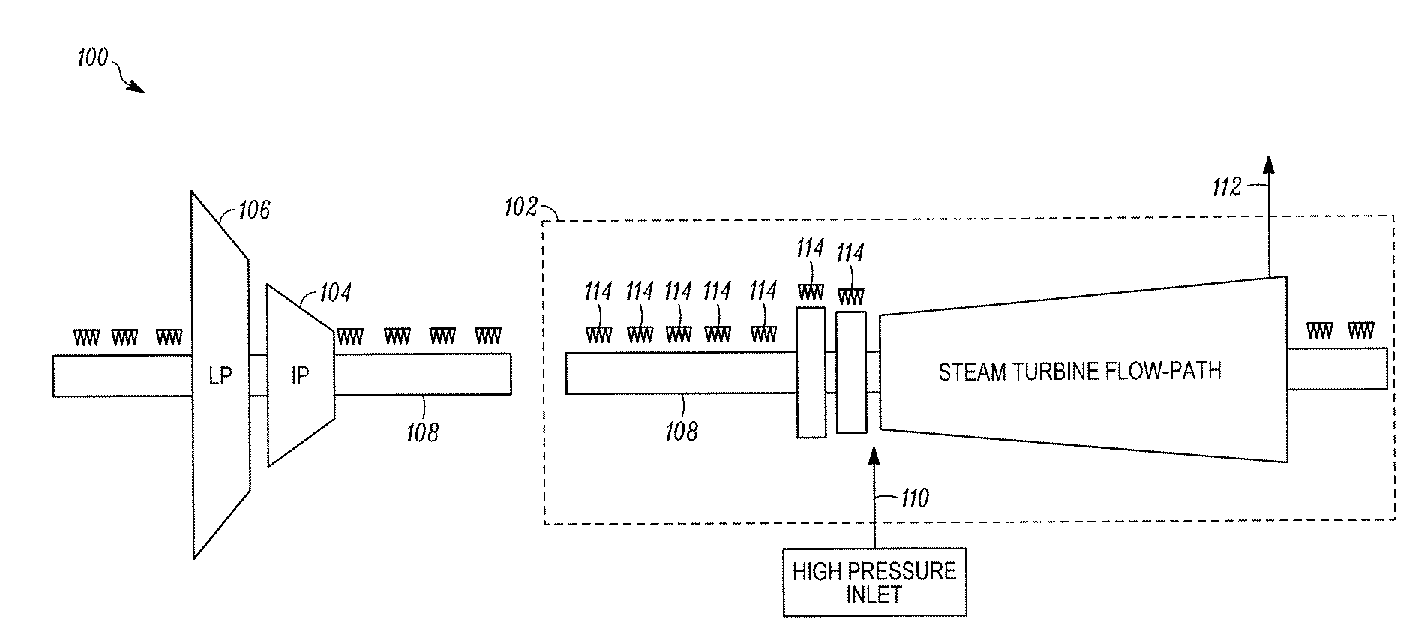
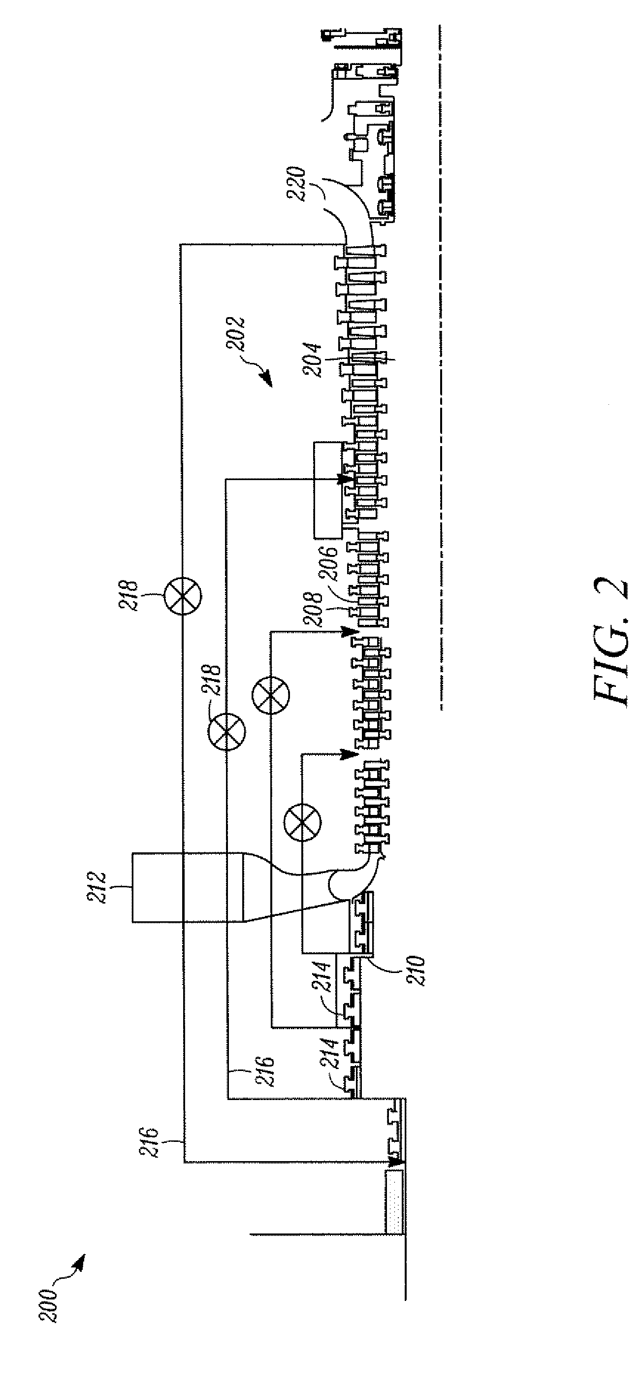
[0006]According to one embodiment of the invention, there is disclosed a method for controlling end gas leakage in a turbine. The method may include providing a plurality of seals in series to reduce gas backflow from an inlet of a turbine. The method may further include providing one or more channels that direct at least a portion of the gas backflow from respective points within the plurality of seals to corresponding points within a gas flow path of the turbine. The portion of the gas backflow may be directed to the points within the gas flow path through the one or more channels.
[0007]According to another embodiment of the invention, there is disclosed a system for controlling gas leakage in a turbine. The system may include a plurality of seals and one or more channels. The plurality of seals may be arranged in series, where each of the plurality of seals may be operable to reduce gas backflow from an inlet of a turbine. The one or more channels may be operable to direct at least a portion of the gas backflow from respective points within the plurality of seals to corresponding points within a gas flow path of the turbine.
[0008]According to yet another embodiment of the invention, there is disclosed a turbine. The turbine may include a casing, a turbine component, an inlet, a plurality of seals, and one or more channels. The casing may surround or envelope the turbine component. The turbine component may include a rotor and a plurality of rotating blades extending from the rotor. The turbine component may be in flow communication with the inlet, and the inlet may provide a gas flow to the turbine component. The plurality of seals may be arranged in series proximate to the inlet, and the plurality of seals may be operable to reduce gas backflow. The one or more channels may be operable to direct at least a portion of the gas backflow from respective points within the plurality of seals to corresponding points within a gas flow path of the turbine component.

Problems solved by technology

Moreover, the extraction of the energy from the various stages is accompanied by losses in each of the individual stages, individual casings and the entire turbine.
For example, in a casing associated with a high pressure (HP) stage of a turbine, losses may occur in the form of end and inter-stage leakages.
The leakage flows reduce the amount of flow in the steam path, leading to a reduction in the amount of work done by the flow, in turn affecting the performance of the turbine.
The leakage flows often lead to degradations in turbine performance.
While these attempts may result in a decrease in the leakage flows, a relatively significant leakage flow may remain in the turbine.

Method used


Image

  • Systems, Methods, and Apparatus for Controlling Gas Leakage in a Turbine
  • Systems, Methods, and Apparatus for Controlling Gas Leakage in a Turbine
  • Systems, Methods, and Apparatus for Controlling Gas Leakage in a Turbine

Examples


Embodiment Construction

[0015]Illustrative embodiments of the invention now will be described more fully hereinafter with reference to the accompanying drawings, in which some, but not all embodiments of the invention are shown. Indeed, the invention may be embodied in many different forms and should not be construed as limited to the embodiments set forth herein; rather, these embodiments are provided so that this disclosure will satisfy applicable legal requirements. Like numbers refer to like elements throughout.

[0016]Disclosed are systems, methods and apparatus for controlling gas leakage in a turbine. Various embodiments of the invention may include a plurality of seals arranged in series and operable to receive a gas backflow in one or more components of a turbine. In certain embodiments, the plurality of seals may include a plurality of packing rings. The pressure of the gas backflow may be reduced as the gas backflow flows across the plurality of seals or packing rings. The plurality of seals may b...


PUM


Abstract

Systems, methods and apparatus for controlling gas leakage in a turbine are provided. A plurality of seals may be provided in series, where each of the plurality of seals may be operable to reduce gas backflow from an inlet of a turbine component. Further, one or more channels may be provided that are operable to direct at least a portion of the gas backflow from respective points within the plurality of seals to corresponding points within a gas flow path of the turbine. The at least a portion of the gas backflow may be directed to the points within the gas flow path through the one or more channels. Additionally, the diameters of the plurality of seals may be optimized to at least partially balance the net thrust generated by the gas flow path of the turbine.

Description

FIELD OF THE INVENTION[0001]Embodiments of the invention relate generally to turbines and more specifically, to systems, methods, and apparatus controlling gas leakage in turbines.BACKGROUND OF THE INVENTION[0002]A turbine typically includes a plurality of turbine stages arranged in series. Each stage often includes a rotating component and a stationary component. Energy is extracted from the gas flow path in each of these stages, and is converted into rotational energy of the rotating component, leading to a pressure drop across each of the individual stages. This pressure drop across each of the individual stages gives rise to a net thrust within the turbine. It is often desirable to balance the thrust produced in order to reduce the mechanical stresses on the turbine.[0003]Moreover, the extraction of the energy from the various stages is accompanied by losses in each of the individual stages, individual casings and the entire turbine. For example, in a casing associated with a hi...

Claims


Application Information

Patent Timeline
Patent Type & Authority Applications(United States)
IPC IPC(8): F01D11/00F16J15/40
CPCF01D3/04F01D11/003F05D2240/61F01D11/04F02C7/28F05D2220/31F05D2240/63
Inventor REN, WEI-MIN
Owner GENERAL ELECTRIC CO
Learn More