
Controlling the configuration of a transmission path

a transmission path and configuration technology, applied in the direction of radio transmission, correct operation testing, electrical equipment, etc., can solve the problems that the mode may not be optimal for other types of transactions, and achieve the effect of reducing the amount of data required, improving efficiency, and poor performan

Inactive Publication Date: 2007-06-21
ARM LTD
View PDF1 Cites 1 Cited by
  • Summary
  • Abstract
  • Description
  • Claims
  • Application Information

AI Technical Summary

Benefits of technology

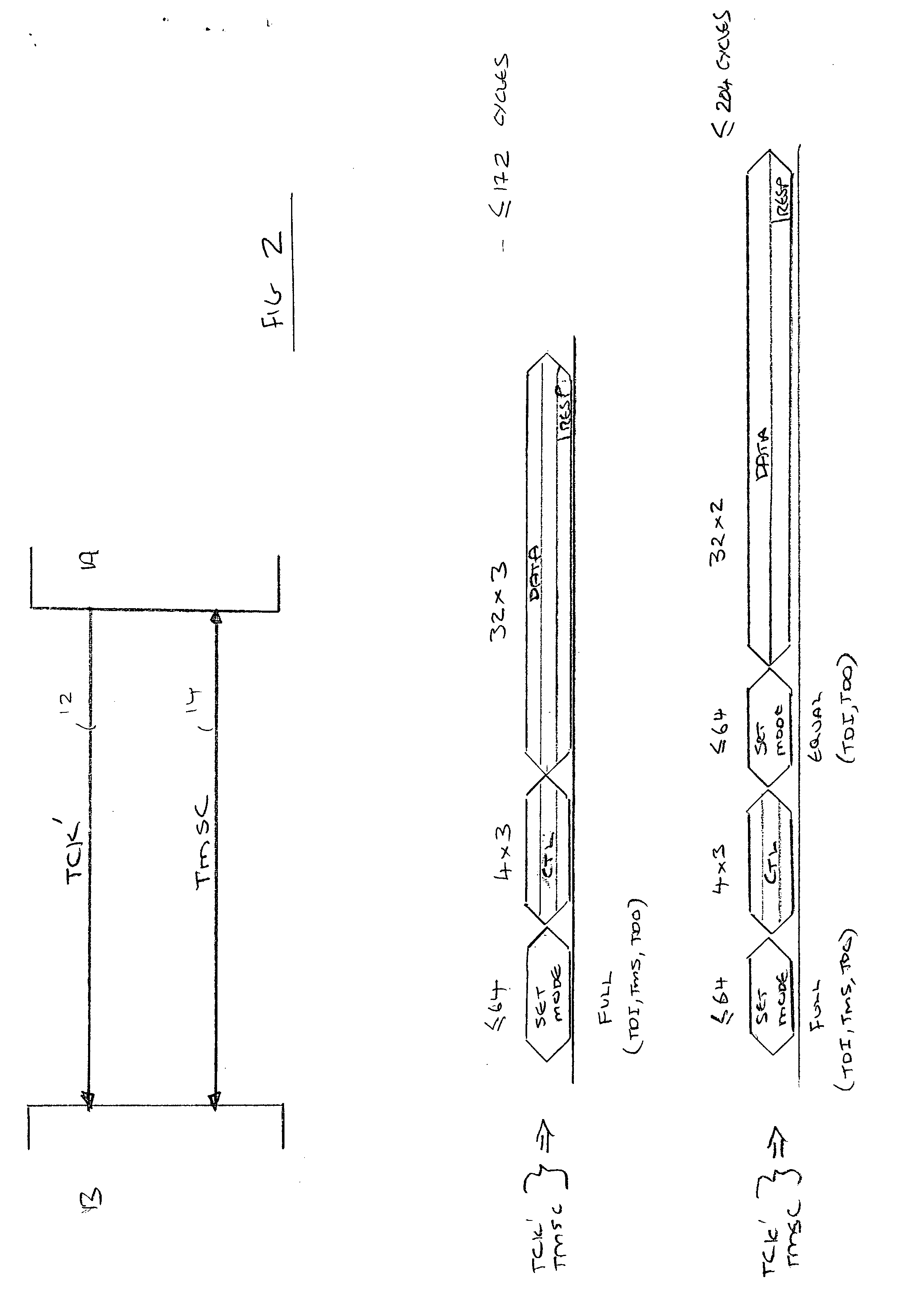
The present invention provides a method for controlling the configuration of a transmission path coupling two units by programming control logic in each unit with an ordered list of modes. The modes are selected based on the type of information items to be transmitted over the path. The control logic is designed to switch between modes efficiently, improving the efficiency of transactions performed over the interface. The method allows for the efficient use of modes that are particularly effective for uni-directional or bi-directional data transfer, reducing the complexity of programming the units. The method also reduces the amount of data required to indicate the new mode, improving the efficiency of total data transaction. The invention provides a mechanism for switching between modes efficiently, synchronizing modes in the two units, and improving the efficiency of transmission over the SJ interface.

Problems solved by technology

The present invention recognises that whilst some interfaces, such as the SJ interface, provides modes which are particularly efficient for transactions where the data transfer is uni-directional or where each bit of data-in has a corresponding bit of data-out, these modes may not be not optimal for other types of transactions.

Method used


Image

  • Controlling the configuration of a transmission path
  • Controlling the configuration of a transmission path
  • Controlling the configuration of a transmission path

Examples


Embodiment Construction

[0079]FIG. 3A illustrates a system 10 including an arrangement of a SJ interface according to one embodiment of the present invention. A TCK′ path 12 and a TMSC path 14 couple a data processing apparatus 20 with a debugger 30. The data processing apparatus 20 receives the TCK′ path 12 and the TMSC path 14 at a SJ interface unit 22. The configuration of the SJ interface unit 22 is controlled by a controller 24. The controller 24 is responsive to a state machine 26 which provides configuration information to be used by the controller 24 when configuring the SJ interface unit 22. Similarly, the debugger 30 receives the TCK′ path 12 and the TMSC path 14 at a SJ interface unit 32. The configuration of the SJ interface unit 32 is controlled by a controller 34. The controller 34 is responsive to a state machine 36 which provides configuration information to be used by the controller 34 when configuring the SJ interface unit 32.

[0080] In this embodiment, the state machine 26 and the state ...


PUM


Abstract

A method, system and unit for controlling the configuration of a transmission path coupling a first unit and a second unit is disclosed. The first unit and the second unit are configurable to support the transfer of information items over the transmission path in time-slots of successive transmission frames in accordance with a plurality of modes, each of the plurality of modes allocating differing numbers of time-slots within each frame to different types of information items. The method comprises the steps of: programming control logic of the first unit and the second unit with an indication of an ordered subset of the plurality of modes to be supported by the first unit and the second unit; configuring the first unit and the second unit to support the transfer the information items over the transmission path using a default one of the plurality of modes; and responsive to an indication requesting that a different mode be selected, causing the first unit and the second unit to be configured to support the next in the ordered subset of the plurality of modes indicated by the control logic. By providing within each unit a predetermined ordered list of modes to be supported by those units, it is only necessary to provide an indication that some change is required and the mode which needs to be changed to can be determined simply by referring to the ordered list. It will be appreciated that this provides a mechanism to switch efficiently between modes, significantly reduces the amount of data required to indicate the new mode and may improve the efficiency of total data transaction.

Description

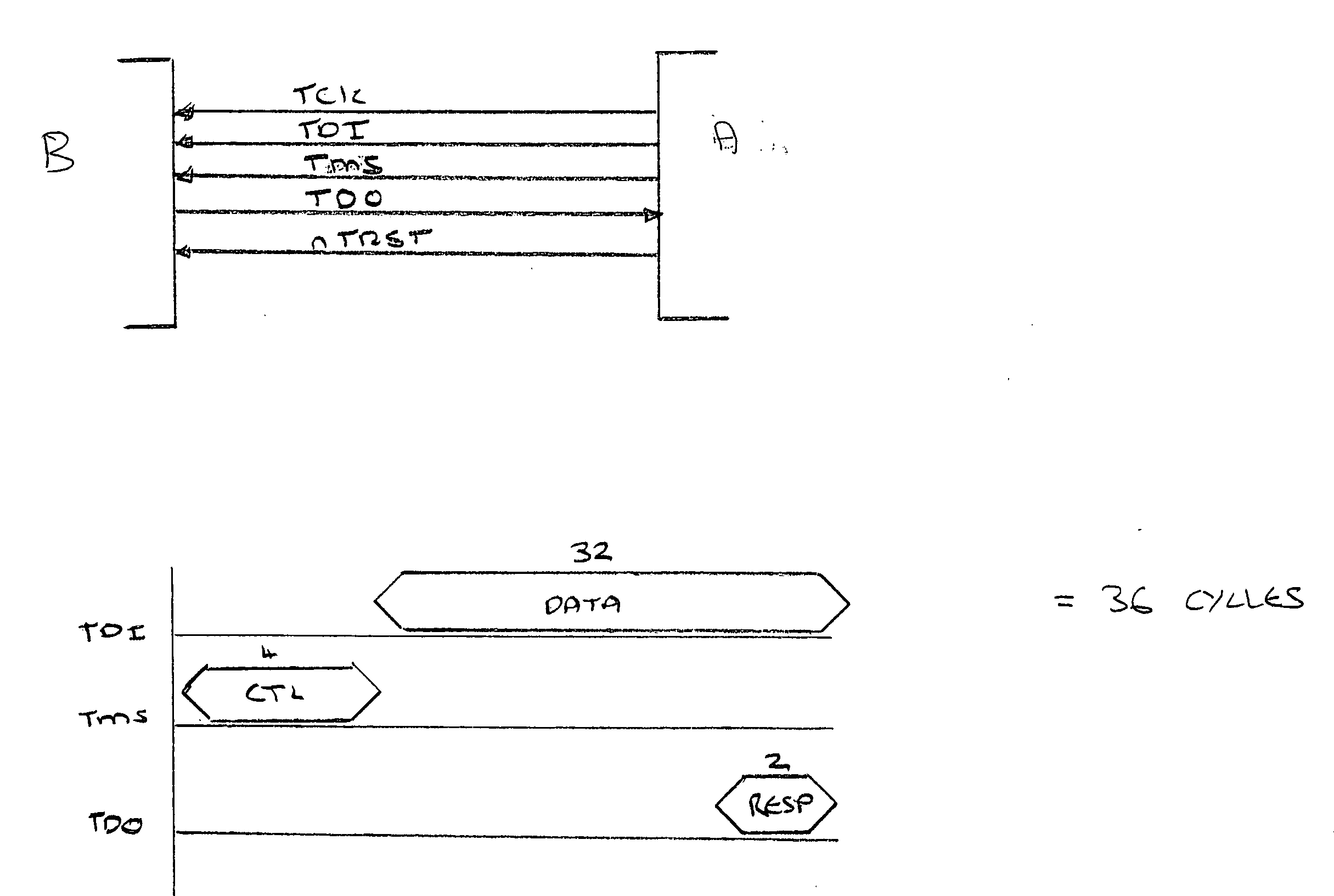
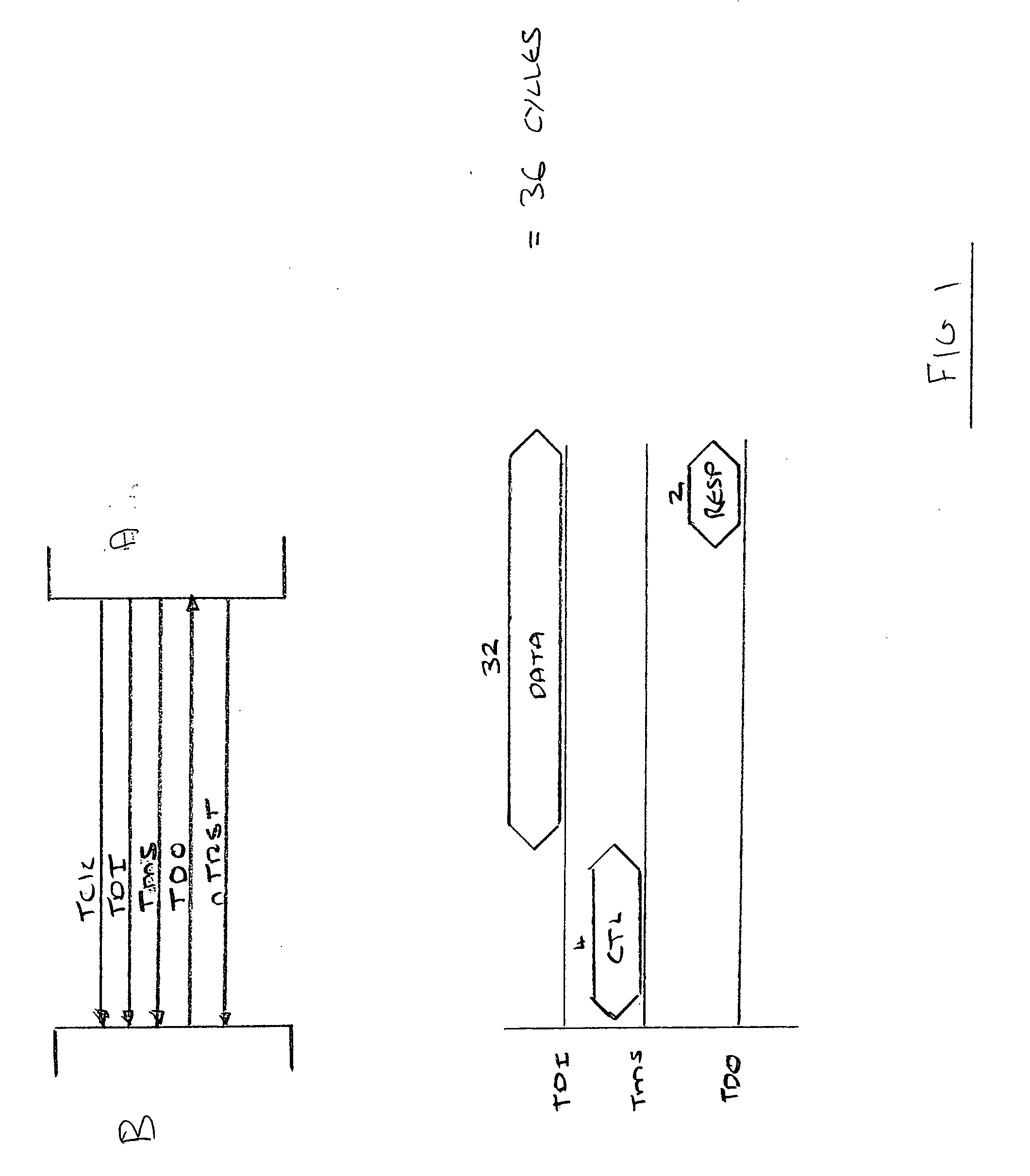
BACKGROUND OF THE INVENTION [0001] 1. Field of the Invention [0002] The present invention relates to techniques for controlling the configuration of a transmission path. Embodiments of the present invention relate to controlling the configuration of a transmission path coupling units, the transmission path being configurable to transfer information items between the units in accordance with a plurality of modes. [0003] 2. Description of the Prior Art [0004] It is often required to control the configuration of a transmission path coupling units. For example, during the debug of a data processing apparatus, it is necessary to control the configuration of a transmission path coupling the data processing apparatus being debugged with a debugger in order to enable the transfer of information items therebetween. [0005] In one known arrangement, there is provided a so-called “JTAG” interface for coupling a debugger A with a data processing apparatus B, as illustrated in FIG. 1. In this arr...

Claims


Application Information

Patent Timeline
Patent Type & Authority Applications(United States)
IPC IPC(8): H04J3/16
CPCH04L1/24
Inventor HOULIHANE, THOMAS SEANASHFIELD, EDMOND JOHN SIMON
Owner ARM LTD
Learn More