
Biological photometric equipment

a technology of biochemical and photometric equipment, applied in the field of biochemical photometric equipment, can solve the problems of increasing the transmission light noise, increasing the load on the trial subject, and increasing the time required for measurement, so as to reduce the measurement error, improve the accuracy of measurement, and improve the effect of precision

Inactive Publication Date: 2007-06-14
HITACHI LTD
View PDF4 Cites 12 Cited by
  • Summary
  • Abstract
  • Description
  • Claims
  • Application Information

AI Technical Summary

Benefits of technology

[0018] As described above, when the transmission factor becomes smaller, there is no way but to increase a gain of an amplifier up to a level allowing detection of a transmitted light signal, with the result that noises caused by transmitted light from the device increase (See FIG. 5).
[0040] Furthermore, when information on both a first living thing and a second living thing are to be acquired with high precision, assuming that sign a denotes a ratio of intensity of light in a first wavelength range directed to a region X of a trial subject against that in a second wavelength range substantially minimizing a measurement error included in information concerning a first measure living body and also that sign b denotes a ratio of intensity of light in a first wavelength range directed to the region X of a trial subject against that in a second wavelength range substantially minimizing a measurement error included in information concerning a second living body, by directing the light changing the light irradiation intensity from time to time between a and b, measurement errors included in information concerning all of the living bodies can substantially be reduced at most.

Problems solved by technology

As the number of times of addition increases, a period of time required for measurement becomes longer and a load to a trial subject becomes more serious.
When the transmitted light intensity is low, it is necessary to raise a gain in detection, which increases the transmitted light noises.
However, when safety to an organism is taken into consideration, it is impossible to raise the irradiation intensity infinitely.

Method used


Image

  • Biological photometric equipment
  • Biological photometric equipment
  • Biological photometric equipment

Examples


Embodiment Construction

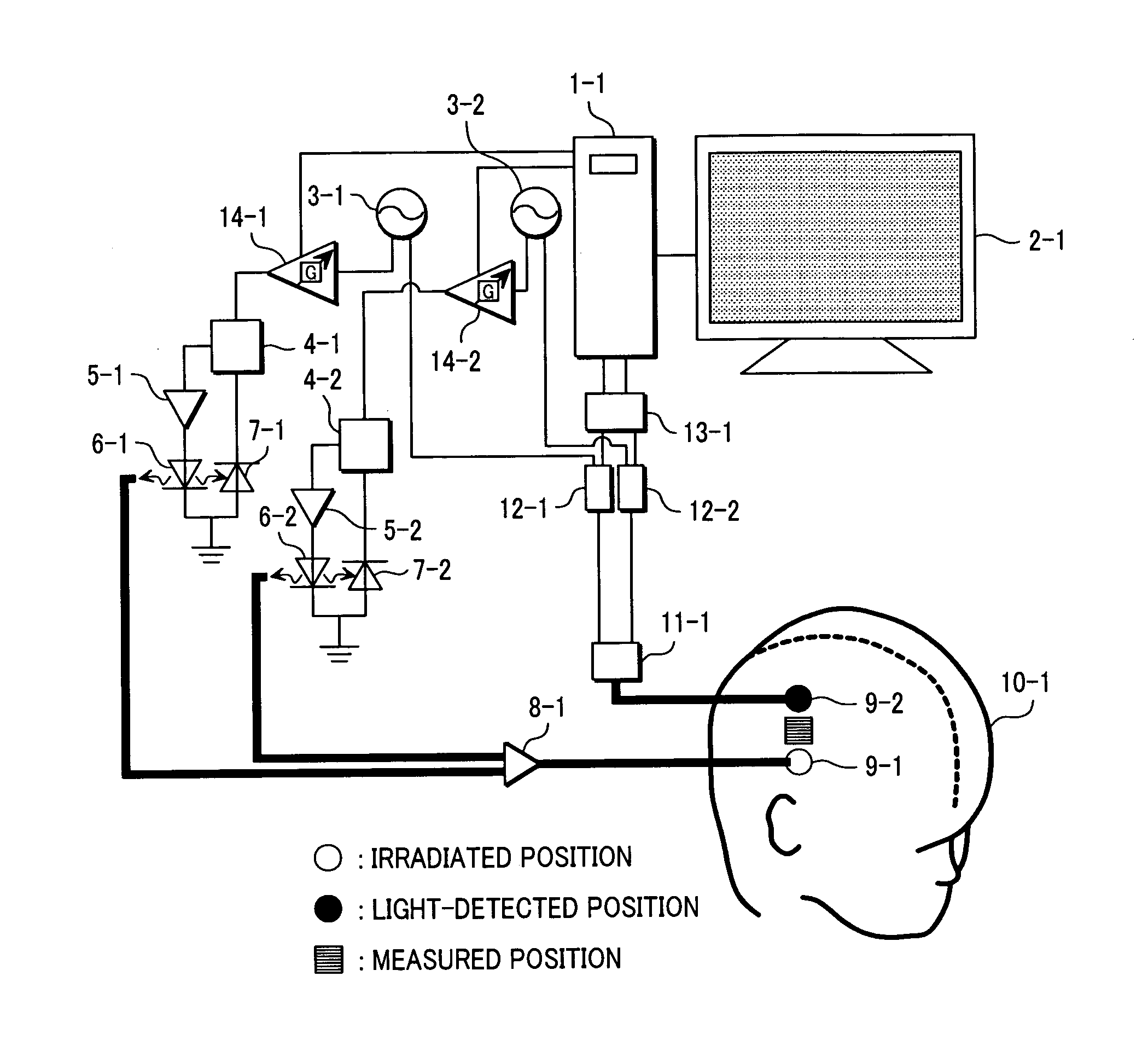
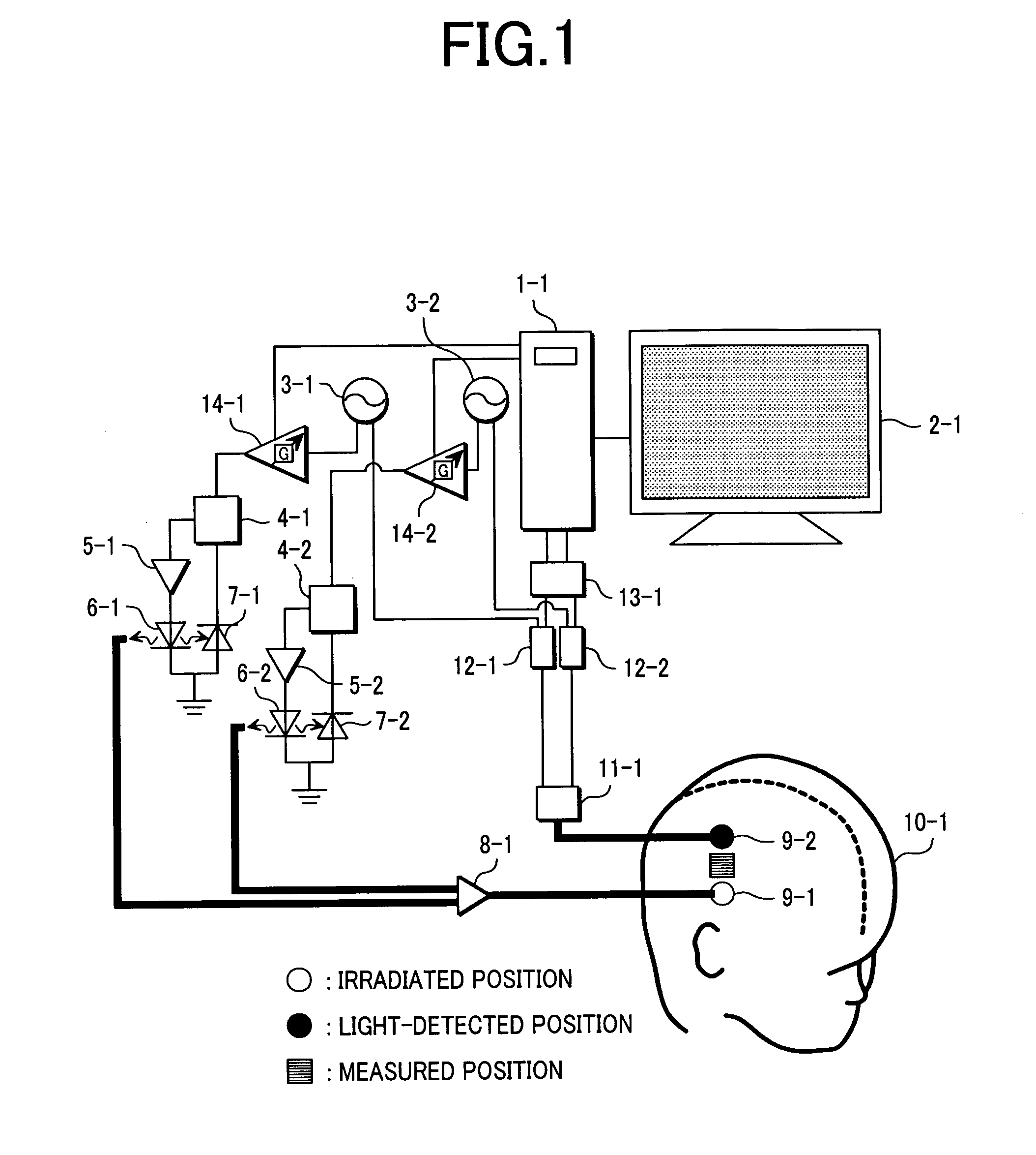
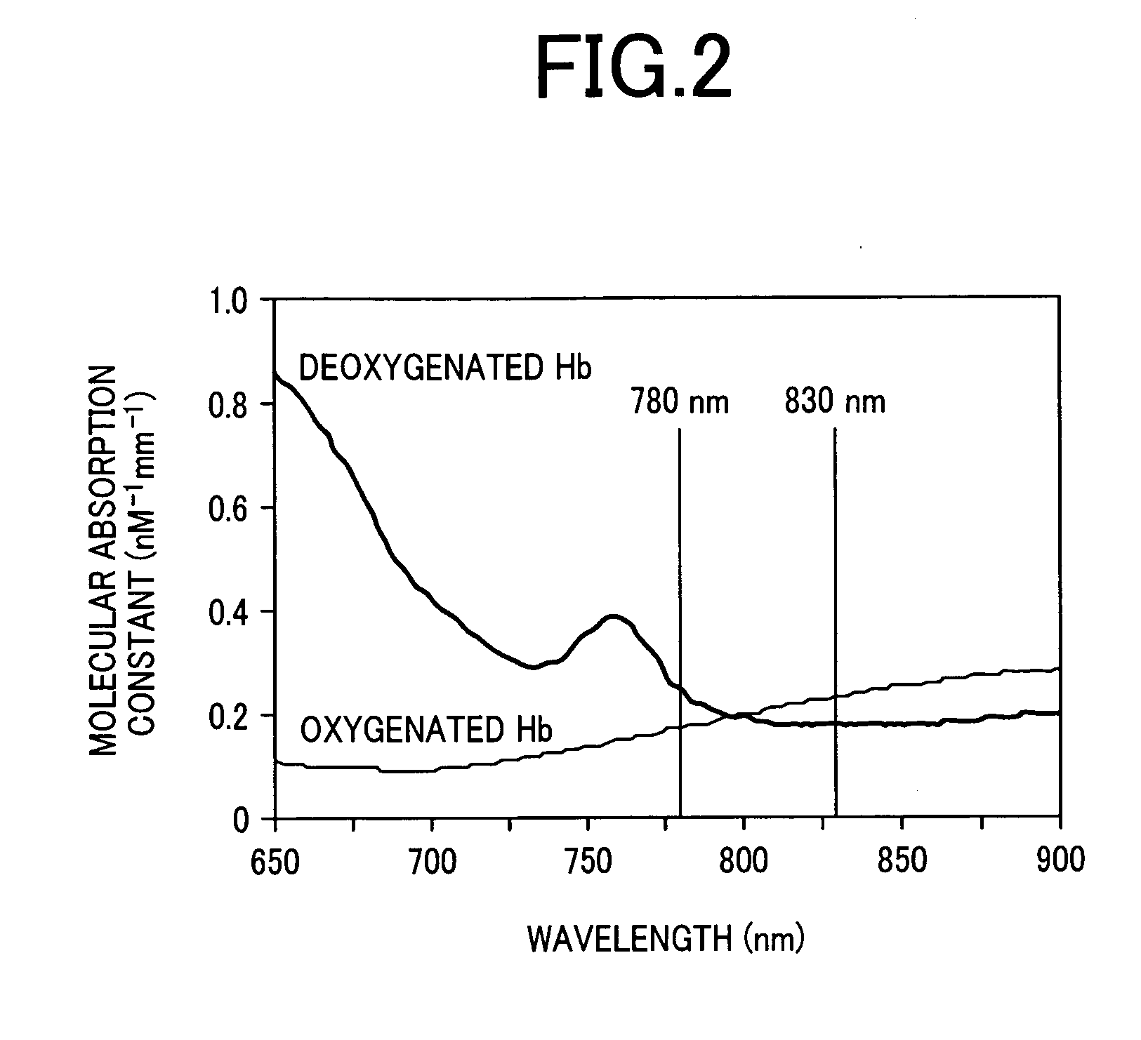
[0057] An embodiment of the present invention will be described below. In this embodiment, for measurement of changes in densities of oxygenated Hb and deoxygenated Hb in a living body, two types of light different in peak wavelength from each other are used to set a light irradiation position and a light receiving position at respective positions. The same measurement can be performed even when the number of wavelength ranges of irradiated light and of positions for irradiation and receiving light are increased.

[0058]FIG. 16 illustrates a case in which regions to be measured are defined on a trial subject in lattice form and light irradiating units and light receiving units are alternately arranged on nodes of the lattice. A helmet-like anchoring tool 16-3 is set on a trial subject 16-4 and optical fibers for light irradiating units 16-1 and light receiving units 16-2 arranged in lattice form are fixed to holes provided in the anchoring tool. With this configuration, changes in de...


PUM

PropertyMeasurementUnit
wavelengthaaaaaaaaaa
wavelength rangeaaaaaaaaaa

Abstract

To control information obtained from inside of a living body with higher precision as compared to that in the conventional technology by controlling a ratio of intensities of light, directed to a trial body, in a plurality of wavelength ranges different in peak wavelength from each other, a measurement error included in information obtained from the living body can be controlled by changing a ratio of intensity of the light in the first wavelength range against that of the light in the second wavelength range. When intensity of irradiated light is limited from the viewpoint of safety to the trial subject, by keeping a ratio of the light irradiated to the trial body in the first wavelength range against that of the light in the second wavelength range under a prespecified value and also by changing the ratio of irradiated light intensities under the prespecified value, a measurement error included in information obtained from the living body can be controlled.

Description

FIELD OF THE INVENTION [0001] The present invention relates to biological photometric equipment, and more specifically to biological photometric equipment for optically measuring information in an organism, especially changes in density of a light-absorbing material. BACKGROUND OF THE INVENTION [0002] It is possible to noninvasively acquire information inside an organism by using light having high transmittance to an organism and also having light intensity peak wavelength (described as peak wavelength hereinafter) in a range from a visual area to a near-infrared area. This technique is based on the Lambert-Beer law indicating that an logarithmic value of a detected optical signal is proportional to a product of a light path length by density. Based on this law, for instance, the technique has been developed for measuring relative changes in density of “oxygenated hemoglobin (Hb)” and “deoxygenated Hb” in an organism. Hb is a substance present in an erythrocyte and important for del...

Claims


Application Information

Patent Timeline
Patent Type & Authority Applications(United States)
IPC IPC(8): A61B5/00A61B5/1455A61B10/00G01N21/27G01N21/35G01N21/359
CPCA61B5/14553
Inventor SATO, HIROKIKIGUCHI, MASSASHIMAKI, ATSUSHIYAMAMOTO, TSUYOSHI
Owner HITACHI LTD
Learn More