
Hydraulic machine

a technology of hydraulic machine and roller, applied in the direction of rotary or oscillating piston engine, engine lubrication, rotary piston engine, etc., can solve the problems of roller being subjected to an especially high load, roller being subjected to a particularly high load, roller edge making a permanent impression, etc., to achieve the effect of improving sealability

Active Publication Date: 2007-06-14
DANFOSS PAUER SOLYUSHENS APS
View PDF4 Cites 4 Cited by
  • Summary
  • Abstract
  • Description
  • Claims
  • Application Information

AI Technical Summary

Benefits of technology

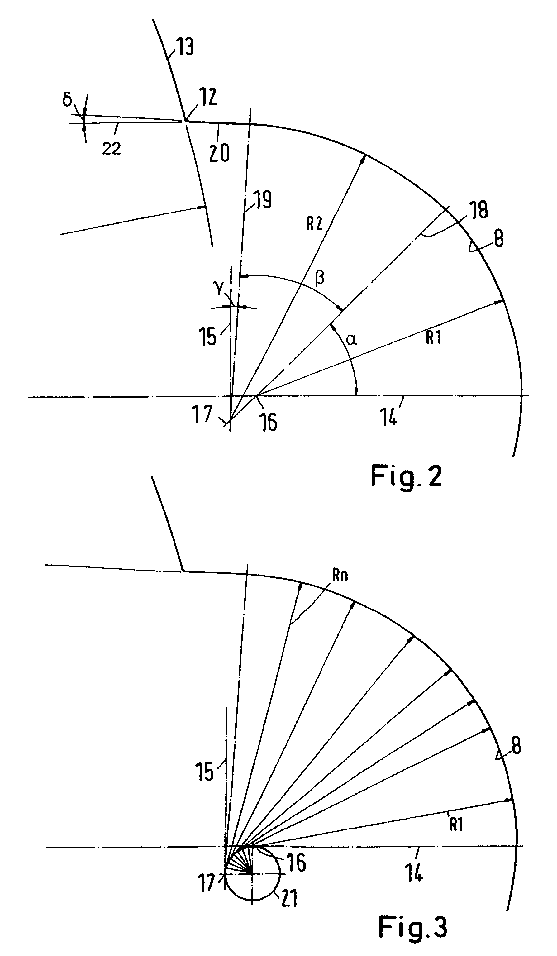
[0010] With such construction, in a middle region of the pocket, the radius of the pocket can be made exactly as large as the radius of the roller, with only a certain play being provided to make sure that the roller can rotate without hindrance. This play is, however, very small; in the order of, for example, two to three hundredths of a millimeter. Therefore, so long as the roller is essentially pressed into the middle of the pocket there results, because of the agreement of the radii of the pocket and the roller, an excellent seal-creating capacity. The associated force imposed on the roller by the gear wheel, which pushes the roller into the pocket, is moreover available during the largest portion of the cycle of the gear wheel because of the prevailing pressure relationships. If, on the other hand, the roller is subjected to a force urging it laterally of the pocket by the pressure in the high-pressure space, the roller can deflect toward the region of the packet with a larger radius. In this deflected position, the roller sees then a larger engagement surface area than if the roller were only engaging the edge of its pocket, so that the surface pressure between the gear ring and the roller is less than in the case of the engagement of the roller on the edge. Also due to the deflection of the roller, it is possible that the forces exerted on the roller will diminish so that the loading of the roll is also decreased.
[0011] Preferably the different radii extend from different axes. Thereby it is, in a simple way, possible to form the outer surface of the pocket, on which the roller lies, as a continuous surface. In other words, there are no corners or discontinuities in the outer surface of the pocket, so that the roller can freely move in the pocket under the influence of corresponding forces without the roller's movement being disturbed.
[0012] Preferably, the axes of the different radii lie on a circular line. This is an especially simple construction for the shifting of the axes, especially when more than two radii are used inside of the pocket.
[0013] Preferably, a radius in the middle of the pocket corresponds to the radius of the roller. This provides the best sealing capability. In this case no exact agreement of the radii is necessary. The radii are of similar enough sizes to achieve the sealing ability.
[0015] Preferably a middle circumferential section of the pocket has a constant radius. In this case upon being loaded the roller lies radially outwardly against the gear ring not only along a line, but over a certain surface area. This improves the sealability because the sealing zone is increased in the circumferential direction.
[0017] Preferably, the pocket has a planar surface connected to each of its edges. This further reduces the risk that the roller comes into contact with an edge of the pocket.

Problems solved by technology

This roller is subjected to an especially high loading.
This higher pressure is especially detrimental if the roller is engaging practically only on the edge of its pocket, where the pocket transitions to the inner surface of the gear ring in the circumferential direction.
Under unfavorable conditions this can lead to the edge making a permanent impression in the roller.
If the roller stands still then no rolling contact occurs between the gear wheel and the roller, and the wear of these components is disproportionately large.
Even without the formation of such an impression, in most cases a considerable wear, either of the edge of the pocket or of the roller, still results.
This wear impairs the sealing ability of the machine and accordingly the machine's efficiency and useful life.
This however, leads to the fact that the point of separation between the high-pressure space and the low-pressure space is not absolutely sealed, which can lead to internal leakage.
To avoid this leakage, expensive pressure delivery measures are required in the pocket.
Also in U.S. Pat. No. 3, 930,766, the pockets have been formed with larger radii than the rollers, which again brings with it sealing problems.

Method used


Image

  • Hydraulic machine
  • Hydraulic machine
  • Hydraulic machine

Examples


Embodiment Construction

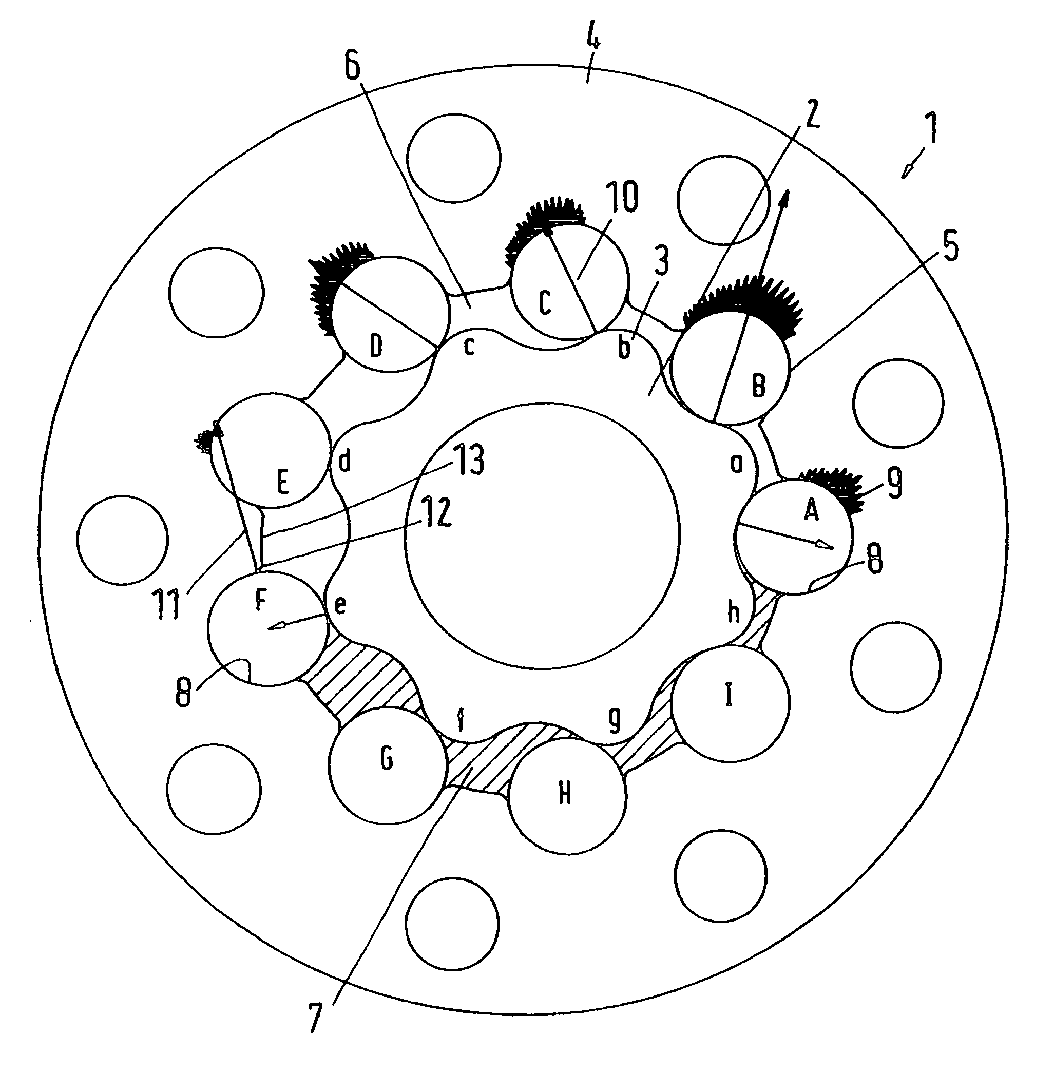
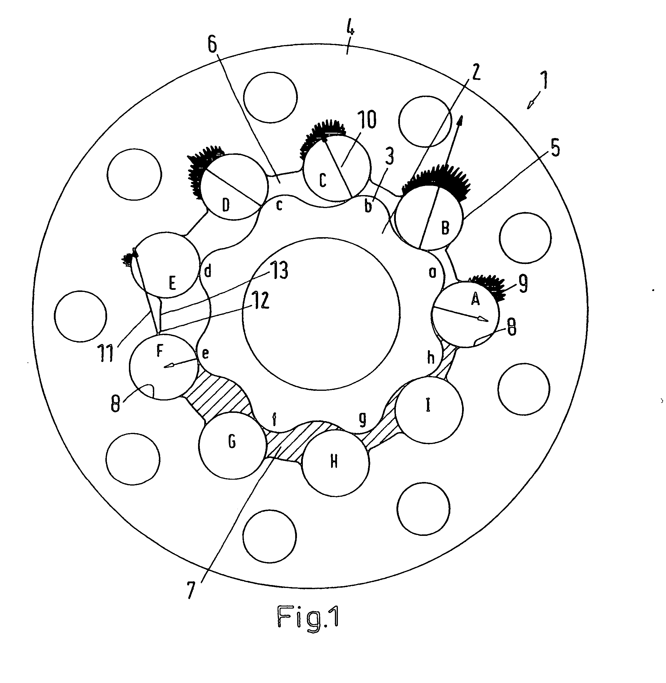
[0025]FIG. 1 shows in schematic illustration a hydraulic machine 1 in cross section, more particularly a displacement section of the hydraulic machine 1. The machine 1 has a gear wheel 2 which, in the present example, has eight teeth 3. To distinguish the teeth from one another they are marked with the letters a-h. The gear wheel 2 is arranged inside of a gear ring 4 which has nine inwardly extending teeth 5 in the form of rollers A-I. The gear ring 4, therefore, has one tooth 5 more than the gear wheel 2 has outwardly extending teeth 3.

[0026] In operation, the gear wheel 2 rotates and orbits inside of the gear ring 4 in a way known manner. As long as no pressure prevails, the gear wheel 2 lies on all of the inwardly extending teeth 5. As soon as the operating pressure prevails, a tight sealing engagement principally occurs only at two positions to form a separation between a low pressure region 6 and a high pressure region 7. The high pressure region 7, for purposes of illustratio...


PUM


Abstract

A hydraulic machine has a gear wheel (2) with outwardly extending teeth and a gear ring (4) with inwardly extending teeth formed by rollers each of which is supported in a pocket (8) in the gear ring, and pressurized spaces are formed between the gear wheel and the inwardly extending teeth. To keep the wear of the machine small each pocket (8) has at least two different radii (R1, R2, Rn) whereby a radius (R2, Rn) at a smaller displacement from the edge (12) of the pocket is larger than a radius (R1) at a larger displacement from the same edge (12) of the pocket (8).

Description

CROSS REFERENCE TO RELATED APPLICATIONS [0001] Applicant hereby claims foreign priority benefits under U.S.C. § 119 from German Patent Application No. 10 2005 058 911.1 filed on Dec. 10, 2005 the contents of which are incorporated by reference herein. FIELD OF THE INVENTION [0002] The invention concerns a hydraulic machine with a gear wheel having outwardly extending teeth and a gear ring having inwardly extending teeth, with the inwardly extending teeth being formed by rollers each of which is located in a corresponding pocket in the gear ring, and wherein pressurized spaces are formed between the gear wheel and the inwardly extending teeth. BACKGROUND OF THE INVENTION [0003] Such a hydraulic machine is known for example from U.S. Pat. No. 3,915,603. The gear wheel rotates and orbits during operation. Between the rollers and the gear wheel the pressurized spaces are formed, of which spaces about one half are filled with hydraulic fluid under high pressure and the remaining half are...

Claims


Application Information

Patent Timeline
IPC IPC(8): F01C1/02F01C1/10F01C1/063F03C2/00
CPCF04C2/084F04C2/10
Inventor PEDERSEN, JOERGENPETERSEN, HANS CHRISTIANJOHANSEN, CLAUS
Owner DANFOSS PAUER SOLYUSHENS APS
Learn More