Optical pickup and optical disc apparatus

a technology of optical discs and pickups, which is applied in the direction of optical recording heads, instruments, data recording, etc., can solve the problems of reducing push-pull operation outputs, affecting the quality of optical discs, so as to improve the amplitude of a tracking error signal and excellent tracking error signals.

Inactive Publication Date: 2007-06-14
SONY CORP
View PDF4 Cites 17 Cited by
  • Summary
  • Abstract
  • Description
  • Claims
  • Application Information

AI Technical Summary

Benefits of technology

[0029] According to an embodiment of the invention, three light beams split by the diffractive element provided with the first to fourth areas having a predetermined periodic structure are separately converged onto the signal recording surface of the optical disc, ea

Problems solved by technology

Thus, there is a problem that an excellent tracking error signal may not be obtained from optical discs 11 having different track pitches, for example, a DVD±R disc and a DVD-RAM disc.
However, in the optical pickup according to the two area in-line DPP method, there is a problem that the displacement of the objective lens is displaced to greatly decrease the push-pull operation outputs of the sub-spots 231 and 232 on the light receiving surface.
However, the optical pickup according to the three area in-line DPP method has the following pr

Method used


Image

  • Optical pickup and optical disc apparatus
  • Optical pickup and optical disc apparatus
  • Optical pickup and optical disc apparatus

Examples


examples

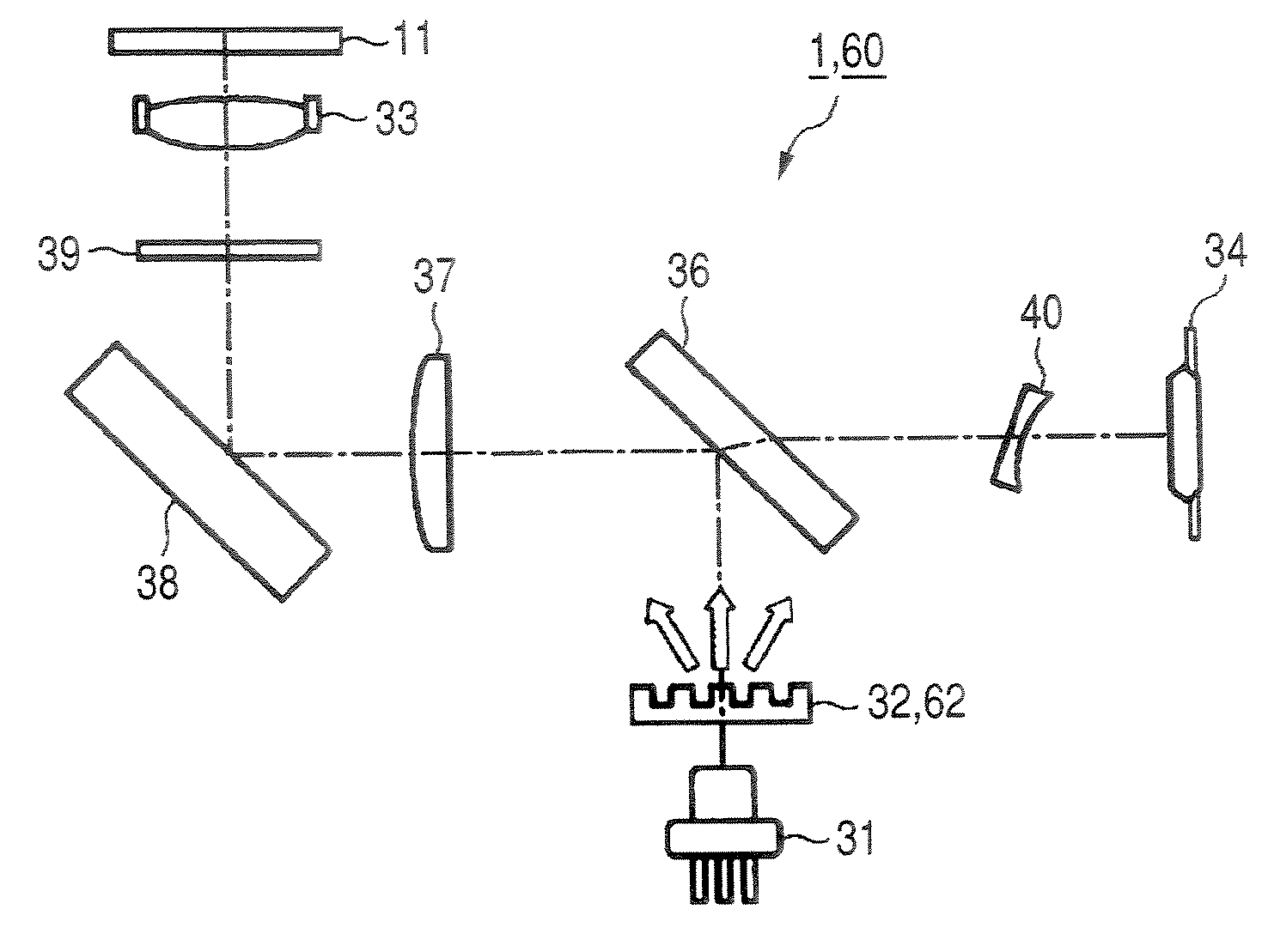
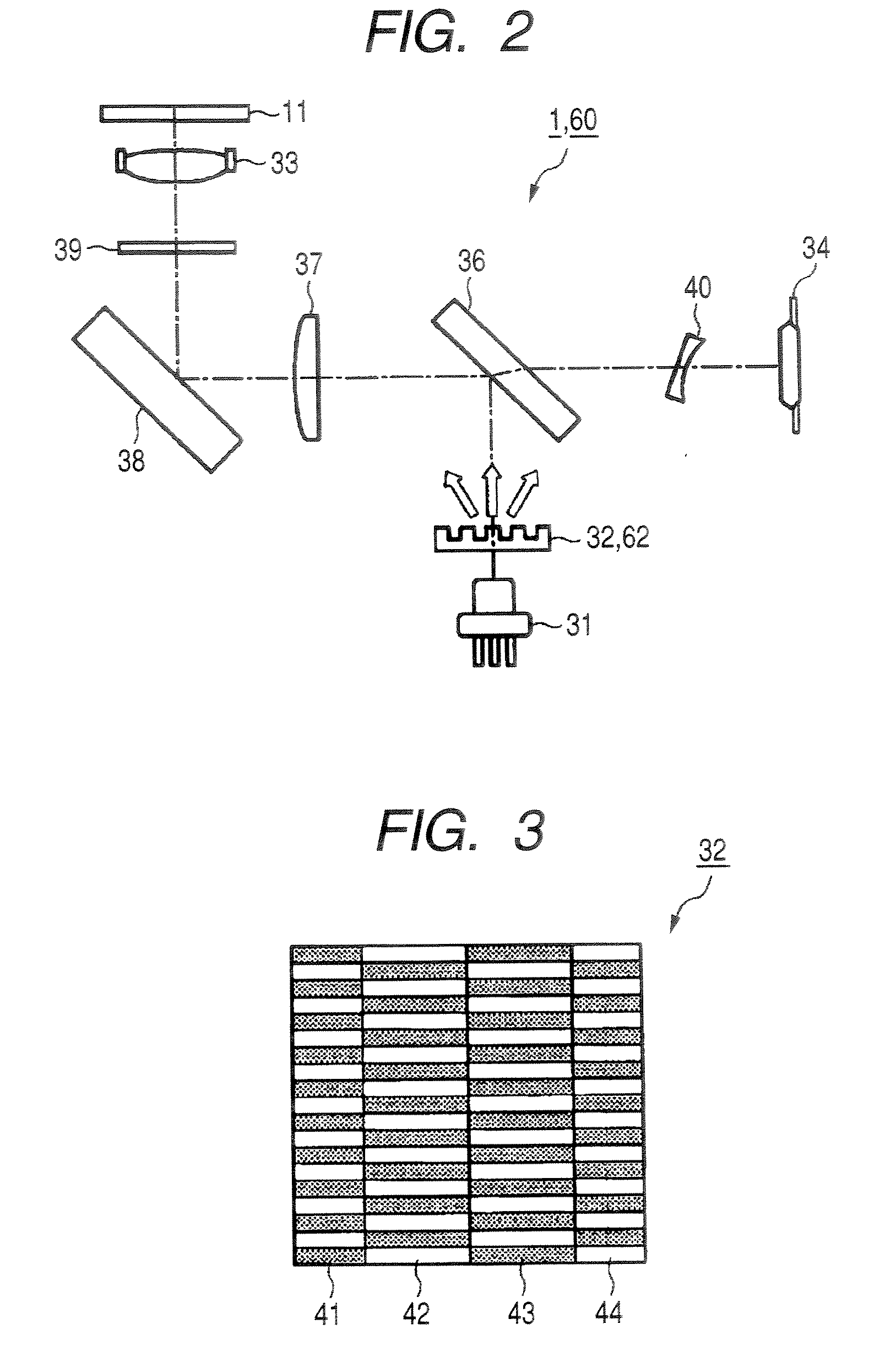
[0151] Hereinafter, for the optical pickups 1 and 60 to which an embodiment of the invention is adapted, specific numeric data is taken for simulation by a computer, and the optimum α1 and α2 will be described based on the result. Here, the following numeric values were used as essential parameters. [0152] (1) Laser beam wavelength: 660 nm [0153] (2) Scaling factor: about 6.5 fold [0154] (3) Objective lens NA: about 0.65 [0155] (4) Focal length of the objective lens: about 2.8 mm [0156] (5) Track pitch of a DVD-RAM disc (guide groove cycle): 1.23 μm [0157] (6) Track pitch of a DVD±R disc (guide groove cycle): 0.74 μm

[0158] Then, FIGS. 12A and 12B show the characteristics of the field of view of the DPP signal amplitude when the numeric data is used for the optical pickup 1 according to the four area in-line DPP method as Example 1. Here, the DPP signal is a tracking error signal. FIG. 12A shows the characteristics of the field of view for a DVD-RAM disc, and FIG. 12B shows the char...


PUM


Abstract

An optical pickup including: a light source; a diffractive element; an objective lens; and a photodetector, wherein the diffractive element has first to fourth areas provided with a predetermined periodic structure in each of the areas, the second and third areas have phases of the periodic structures of the second and third areas varied at an angle of about 180 degrees, the first area has a phase of the periodic structure in the first area varied from a phase of the periodic structure in the second area at an angle of about 180 degrees, and the fourth area has a phase of the periodic structure in the fourth area varied from a phase of the periodic structure in the third area at an angle of about 180 degrees. The optical pickup can obtain an excellent tracking error signal and improved amplitude when the objective lens is displaced.

Description

CROSS REFERENCES TO RELATED APPLICATIONS [0001] The present invention contains subject matter related to Japanese Patent Application JP 2005-310398 filed in the Japanese Patent Office on Oct. 25, 2005, the entire contents of which being incorporated herein by reference. BACKGROUND OF THE INVENTION [0002] 1. Field of the Invention [0003] The present invention relates to an optical pickup and an optical disc apparatus which record and / or reproduce information from an information recording medium such as an optical disc. [0004] 2. Description of the Related Art [0005] In order to record and / or reproduce information from an information recording medium such as an optical disc by an optical pickup, it is necessary to correctly apply a convergence spot onto a predetermined recording track on the optical disc. [0006] In order to correctly apply the convergence spot onto the recording track on the optical disc, a differential push-pull method (hereinafter, it is called a “conventional DPP m...

Claims


Application Information

Patent Timeline
IPC IPC(8): G11B7/00
CPCG11B7/0903G11B7/094G11B7/1353G11B7/1381
Inventor ARAI, MASAKI
Owner SONY CORP
Why Eureka
Try Eureka