Method for discriminating optical discs, and optical disc apparatus
a technology of optical discs and optical discs, applied in the direction of digital signal error detection/correction, instruments, recording signal processing, etc., can solve the problems of increased production cost, complicated configuration, and inability to employ mechanical detection systems, and achieve the effect of largely dropping the amplitude of the produced full adding signal
- Summary
- Abstract
- Description
- Claims
- Application Information
AI Technical Summary
Benefits of technology
Problems solved by technology
Method used
Image

Examples
embodiment 1
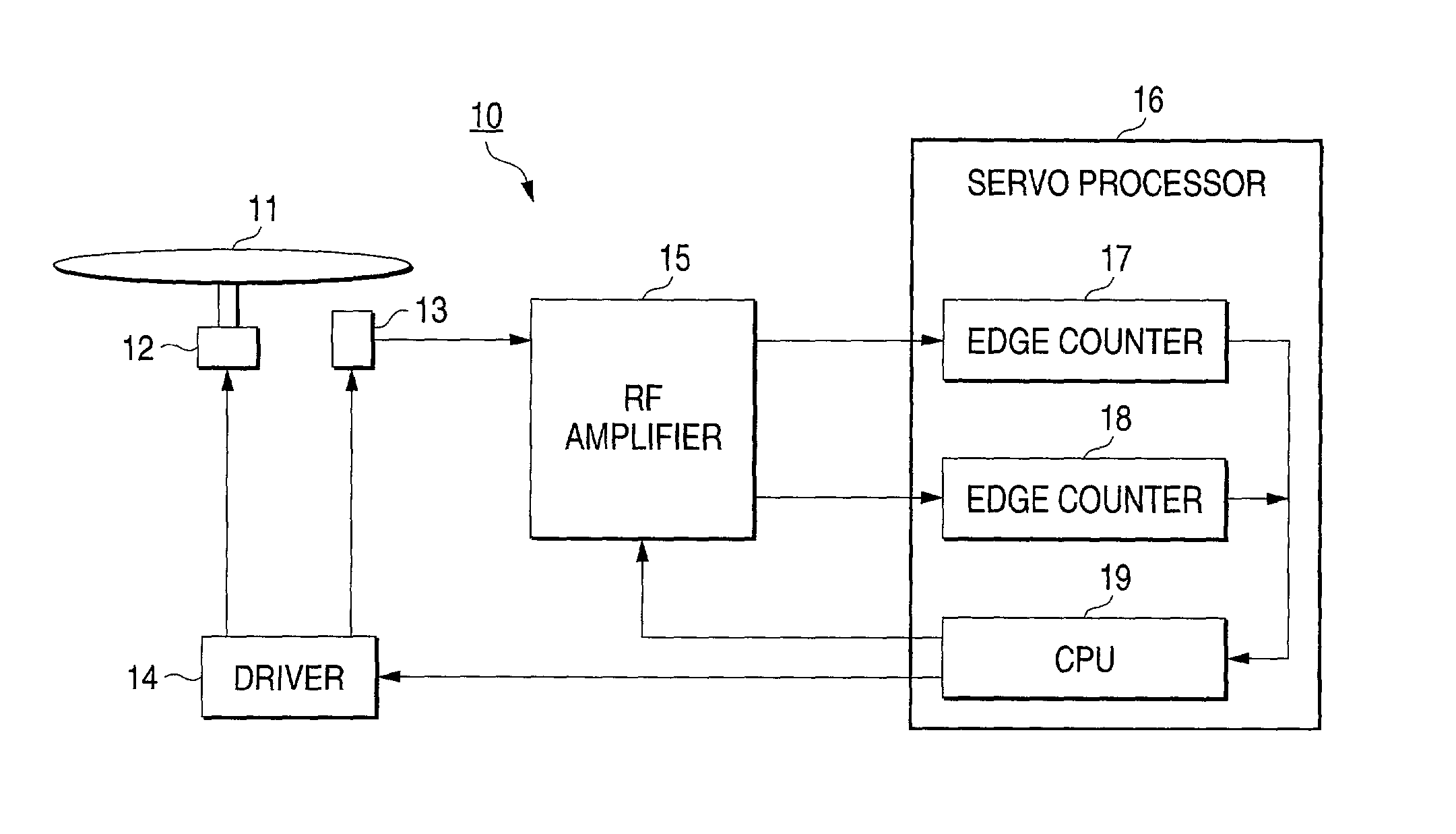
[0059] FIG. 5 is a flowchart showing the operation of the optical disc apparatus 10 of When the optical disc 11 is loaded into the optical disc apparatus 10, the optical pickup 13 is first set in step S30 to a focus-on and track-off state. The control then advances to step S31 to detect signals by driving the optical pickup 13 in a radial direction of the optical disc 11, and operating the optical pickup in the circumferential direction of the optical disc 11 with predetermined amplitude and period. Specifically, signals are detected while the optical pickup 13 is operated so as to move along a standing wave form with respect to the optical disc 11 as indicated by the broken line in FIG. 6. As the standing wave form, for example, a sinusoidal wave form or the like may be used.
[0060] The control advances from step S31 to step S32 to produce the TCs and the MIs in the RF amplifier 15 on the basis of the detected signals. The control then advances to step S33 so that the edge counters...
embodiment 2
[0065] FIG. 9 is a flowchart showing the operation of the optical disc apparatus 10 of When the optical disc 11 is loaded into the optical disc apparatus 10, the optical pickup 13 is first set in step S40 to a focus-on and track-off state. The control then advances to step S41 in which signals are detected by the RF amplifier 15 and the comparison level for detecting the MIs is lowered by the predetermined value. The following steps or steps S42 to S46 are identical with steps S32 to S36 of FIG. 5.
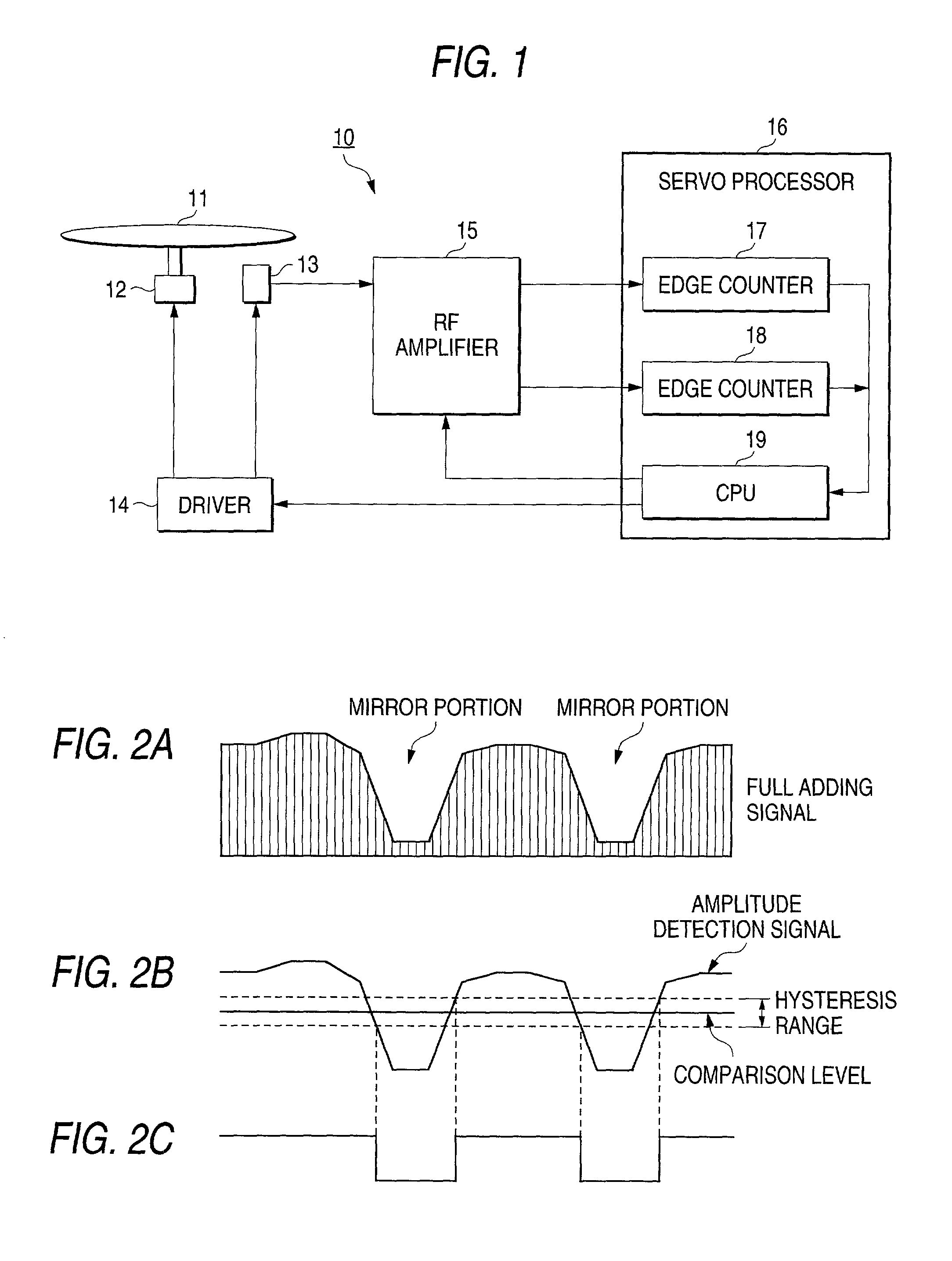
[0066] In FIG. 10, FIG. 10A shows the full adding signal obtained when a CD is loaded, FIG. 10B shows signals such as an amplitude detection signal, and FIG. 10C shows the MIs, and, in FIG. 11, FIG. 11A shows the full adding signal obtained when a DVD is loaded, FIG. 11B shows signals such as an amplitude detection signal, and Fig. 11C shows the MIs.
[0067] In Embodiment 2, the comparison level for detecting the MIs is lowered. In the case of a CD, therefore, the MIs can be detected becaus...
embodiment 3
[0069] FIG. 12 is a flowchart showing the operation of the optical disc apparatus 10 of When the optical disc 11 is loaded into the optical disc apparatus 10, the optical pickup 13 is first set in step S50 to a focus-on and track-off state. The control then advances to step S51 in which signals are detected by the RF amplifier 15 and the hysteresis range of the comparison level for detecting the MIs is increased by the predetermined value. The following steps or steps S52 to S56 are identical with steps S32 to S36 of FIG. 5.
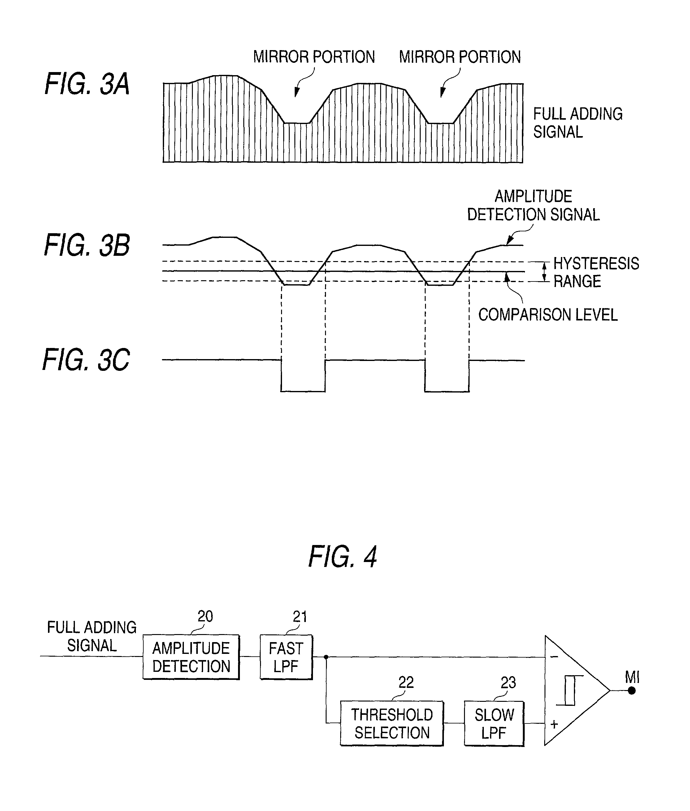
[0070] In FIG. 13, FIG. 13A shows the full adding signal obtained when a CD is loaded, FIG. 13B shows signals such as an amplitude detection signal, and FIG. 13C shows the MIs, and, in FIG. 14, FIG. 14A shows the full adding signal obtained when a DVD is loaded, FIG. 14B shows signals such as an amplitude detection signal, and FIG. 14C shows the MIs.
[0071] In Embodiment 3, the hysteresis range of the comparison level for detecting the MIs is increased by the pre...
PUM
| Property | Measurement | Unit |
|---|---|---|
| diameter | aaaaa | aaaaa |
| distance | aaaaa | aaaaa |
| distance | aaaaa | aaaaa |
Abstract
Description
Claims
Application Information
 - R&D
- Intellectual Property
- Life Sciences
- Materials
- Tech Scout
- Unparalleled Data Quality
- Higher Quality Content
- 60% Fewer Hallucinations
Browse by: Latest US Patents, China's latest patents, Technical Efficacy Thesaurus, Application Domain, Technology Topic, Popular Technical Reports.
© 2025 PatSnap. All rights reserved.Legal|Privacy policy|Modern Slavery Act Transparency Statement|Sitemap|About US| Contact US: help@patsnap.com