Steam floor mop

Active Publication Date: 2007-06-14
SHARKNINJA OPERATING LLC
View PDF32 Cites 54 Cited by
  • Summary
  • Abstract
  • Description
  • Claims
  • Application Information

AI Technical Summary

Benefits of technology

[0006] It is another objective of the present invention to provide a steam floor mop with which the cleaning work can be performed conveniently and is time and labor saving, and the effect of high temperature disinfecting and sterilization can be realized thoroughly.
[0017] As a result, in accordance with the steam floor mop of the present invention, by only pushing the handle of the steam floor mop, the steam can be generated and distributed to the floor brush so that the cleaning work having an effect of high temperature disinfecting and sterilization can be realized. It is not needed to power on the water pump additionally so as to supply water to the steam generator to generate the steam. Besides, a plurality of rib stripes are set on the floor brush, and a plurality of steam distributing grooves are formed between the rib stripes, so that the steam can be distributed uniformly to the whole cleaning surface of the floor brush. In addition, the floor brush is covered tightly by a cleaning cloth having a plurality of #-shaped checks formed thereon, so that the stains adhered to the floor can be cleaned easily. Therefore, by utilizing the steam floor mop of the present invention, the cleaning work can be performed conveniently and is time and labor saving, the effect of high temperature disinfecting and sterilization can be realized thoroughly.

Problems solved by technology

The current floor cleaning mops are generally classified into two types: one is the traditional floor mop, which can be used for the dry cleaning work, and is not suitable to realize a wet cleaning purpose; therefore, its application is limited; the other is the floor cleaning mop having a steam distributing function, with which the water is firstly heated vaporized to generate steam which is then distributed to the floor for the cleaning work so as to realize the effect of high-temperature disinfecting and sterilization.
However, the current steam floor mop has the following drawbacks: when in use, the water needs to be loaded firstly to the steam generator by powering on the water pump additionally, and then is heated vaporized to generate steam for the cleaning work, this process takes such a long time that its application is inconvenient; in addition, the cleaning work has to be performed repeatedly many times in order to obtain a thorough cleaning effect, it is time-consuming and tiring.
The main reasons for the above problems are: most of the cleaning surface of the current mop is flat, which is bad for the steam distributing to the whole cleaning surface, and thus results in the consequence that the cleaning surface can not be wetted uniformly, some portion of the cleaning surface is too dry while some portion is too wet, and that, the effect of high-temperature disinfecting and sterilization can not be realized; moreover, the cleaning cloth serves to cover the floor brush is too smooth without any pattern or stripe that the stains adhered to the floor cannot be cleaned easily.

Method used


Image

  • Steam floor mop
  • Steam floor mop
  • Steam floor mop

Examples


Embodiment Construction

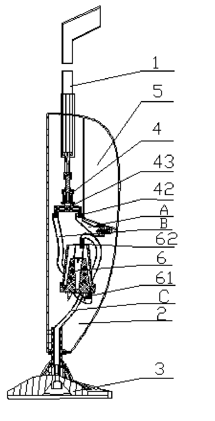
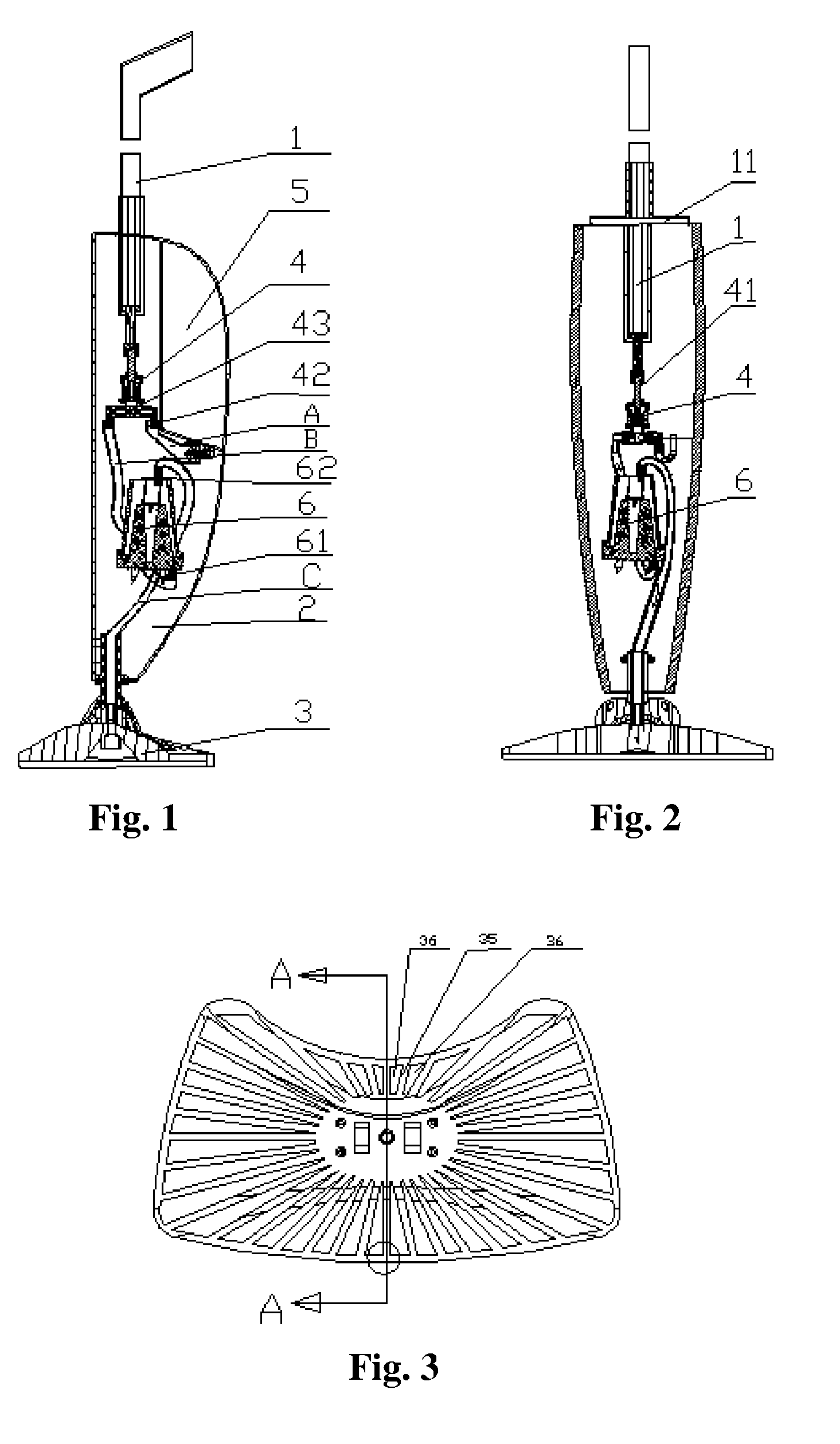
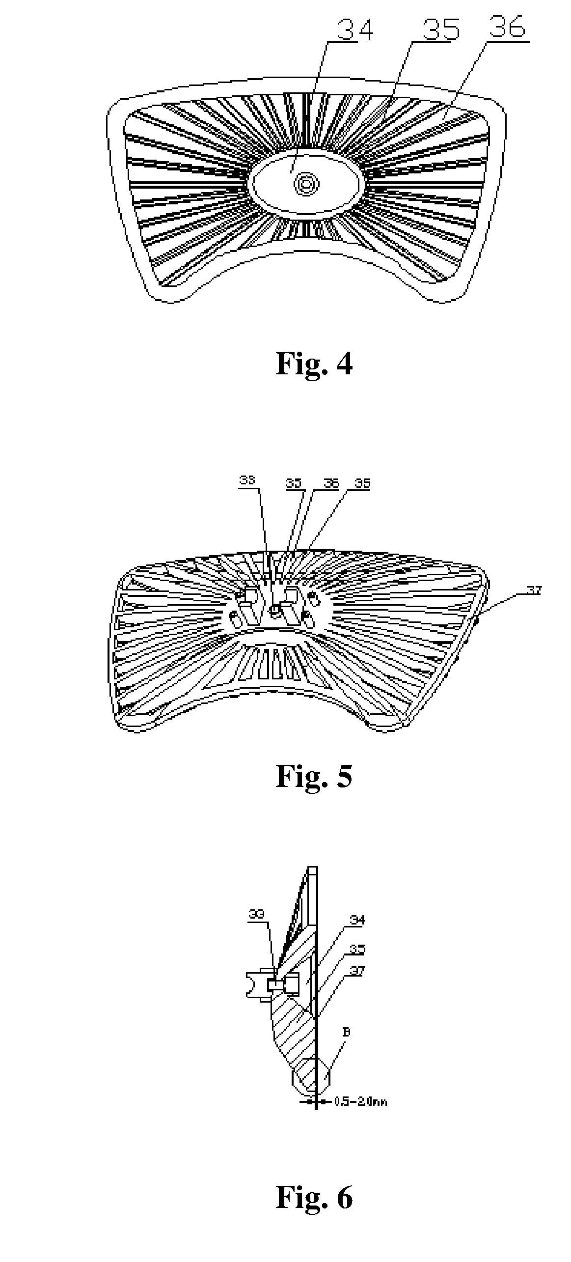
[0030] As shown in FIGS. 1-2, a steam floor mop comprises a handle 1, a central body 2 inside which a manual water pump 4, a water tank 5, and a steam generator 6 are housed; and a floor brush 3 connected flexibly to the bottom end of the central body 1, wherein said handle 1 is connected directly to the piston rod 41 of the manual water pump 4, and serves to manipulate the operation of the manual water pump 4; said floor brush 3 is covered with a cleaning cloth 7. A water inlet mouth 42 and a water outlet mouth 43 are formed at the lower end of said manual water pump 4, wherein said water inlet mouth 42 is connected to the water tank 5 by means of a first pipe A; said water outlet mouth 43 is connected to the water inlet mouth 61 of the steam generator 6 by means of a second pipe B; the steam exit 62 of the steam generator 6 is connected to the floor brush 3 by means of a third pipe C.

[0031] A handle cover 11 that can socket with the handle 1 and serves to limit the moving range o...


PUM


Abstract

The present invention discloses a steam floor mop, comprising a handle; a central body inside which a manual water pump, a water tank, and a steam generator are housed; and a floor brush connected flexibly to the central body, wherein the manual water pump, the water tank, and the steam generator are connected to the floor brush by means of pipes; said handle is connected directly to the piston rod of the manual water pump and serves to manipulate the operation of the manual water pump; said floor brush is covered by a cleaning cloth. In accordance with the steam floor mop of the present invention, by only pushing the handle of the steam floor mop, the steam can be generated and distributed to the floor brush so that the cleaning work having an effect of high temperature disinfecting and sterilization can be realized. It is not needed to power on the water pump additionally so as to supply water to the steam generator to generate the steam. Besides, a plurality of rib stripes are set on the floor brush, and a plurality of steam distributing grooves are formed between the rib stripes, so that the steam can be distributed uniformly to the whole cleaning surface of the floor brush. In addition, the floor brush is covered tightly by a cleaning cloth having a plurality of #-shaped checks formed thereon, so that the stains adhered to the floor can be cleaned easily. Therefore, by utilizing the steam floor mop of the present invention, the cleaning work can be performed conveniently and is time and labor saving, the effect of high temperature disinfecting and sterilization can be realized thoroughly.

Description

BACKGROUND OF THE INVENTION [0001] 1. Field of the Invention [0002] This invention relates to a steam floor mop, and specifically, to a steam cleaning appliance for cleaning work. [0003] 2. Description of the Related Art [0004] The current floor cleaning mops are generally classified into two types: one is the traditional floor mop, which can be used for the dry cleaning work, and is not suitable to realize a wet cleaning purpose; therefore, its application is limited; the other is the floor cleaning mop having a steam distributing function, with which the water is firstly heated vaporized to generate steam which is then distributed to the floor for the cleaning work so as to realize the effect of high-temperature disinfecting and sterilization. However, the current steam floor mop has the following drawbacks: when in use, the water needs to be loaded firstly to the steam generator by powering on the water pump additionally, and then is heated vaporized to generate steam for the cle...

Claims


Application Information

Patent Timeline
IPC IPC(8): A47L11/30
CPCA47L11/34A47L11/4086A47L13/22A47L13/225F22B1/285
Inventor ZHOU, HONG
Owner SHARKNINJA OPERATING LLC
Why Eureka
Try Eureka