
Use of chlorine to fabricate trench dielectric in integrated circuits

a dielectric and integrated circuit technology, applied in the field of integrated circuits, can solve problems such as overerase and/or other problems, and achieve the effects of preventing undue consumption of active area, reducing the oxidation time, and enhancing the corner rounding

Inactive Publication Date: 2007-06-07
DONG ZHONG +1
View PDF12 Cites 2 Cited by
  • Summary
  • Abstract
  • Description
  • Claims
  • Application Information

AI Technical Summary

Benefits of technology

The method effectively rounds trench corners, ensuring uniform tunnel oxide thickness and reducing electric fields, thereby improving the operational reliability of integrated circuits by minimizing active area consumption and preventing overerase.

Problems solved by technology

The oxide thinning further increases the electric field at the corners, creating overerase and / or other problems (depending on the memory operation).

Method used


Image

  • Use of chlorine to fabricate trench dielectric in integrated circuits
  • Use of chlorine to fabricate trench dielectric in integrated circuits
  • Use of chlorine to fabricate trench dielectric in integrated circuits

Examples


Embodiment Construction

[0017] The embodiments described in this section illustrate but do not limit the invention. The invention is not limited to particular fabrication techniques or numerical values and ranges. The invention is defined by the appended claims.

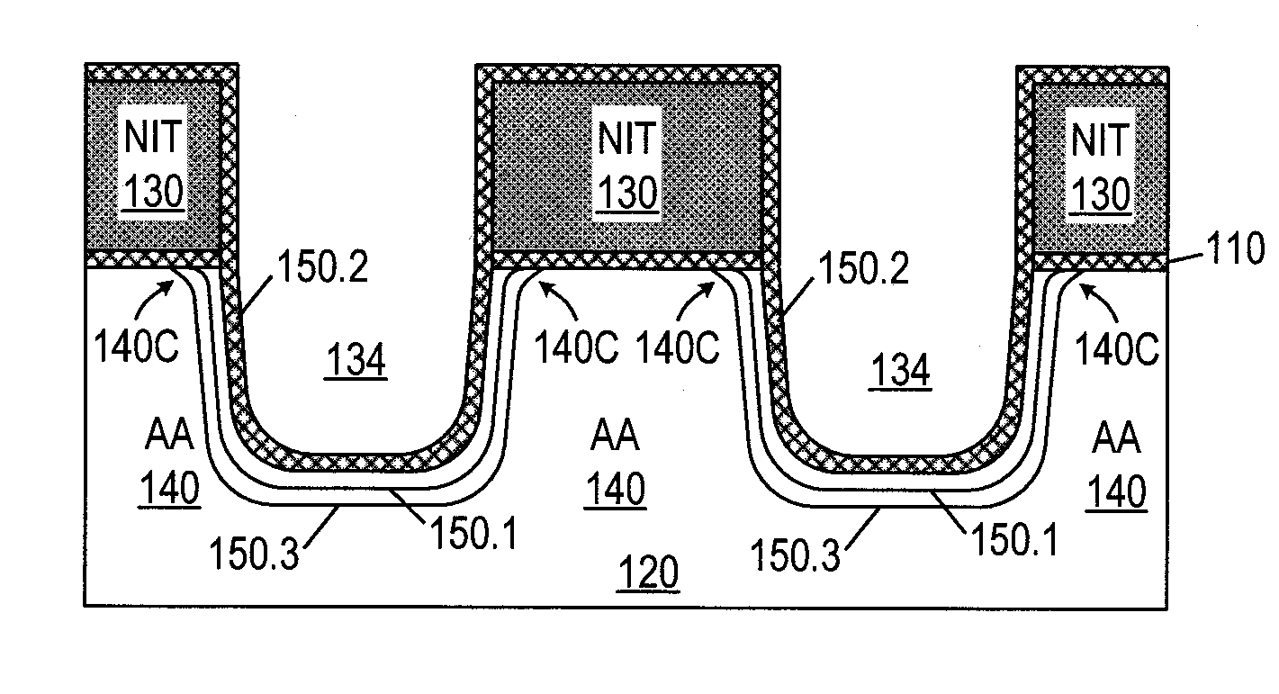
[0018]FIG. 9 illustrates initial STI fabrication stages in one embodiment of the present invention. Silicon dioxide layer 110 comprising chlorine atoms is formed on silicon wafer 120. In some embodiments, the chlorine concentration is more than three atomic percent, or at least 5 atomic percent. A range from 5 to 15 atomic percent is believed to be suitable, and other concentrations are possible.

[0019] In one embodiment, oxide 110 is formed by thermal oxidation at 800˜1000° C. The oxygen flow is 10±5 l / m in (liters per minute). The chlorine is provided by hydrogen chloride (HCl) flown at 1 l / min. Other possible chlorine sources include the chlorine gas (Cl), TCA (trichloroethane, C2H3Cl3), TCE (trichloroethylene, C2HCl2), dichloroethylene (C2H2Cl2...


PUM


Abstract

Chlorine is incorporated into pad oxide (110) formed on a silicon substrate (120) before the etch of substrate isolation trenches (134). The chlorine enhances the rounding of the top corners (140C) of the trenches when a silicon oxide liner (150.1) is thermally grown on the trench surfaces. A second silicon oxide liner (150.2) incorporating chlorine is deposited by CVD over the first liner (150.1), and then a third liner (150.3) is thermally grown. The chlorine concentration in the second liner (150.2) and the thickness of the three liners (150.1, 150.2, 150.3) are controlled to improve the corner rounding without consuming too much of the active areas (140).

Description

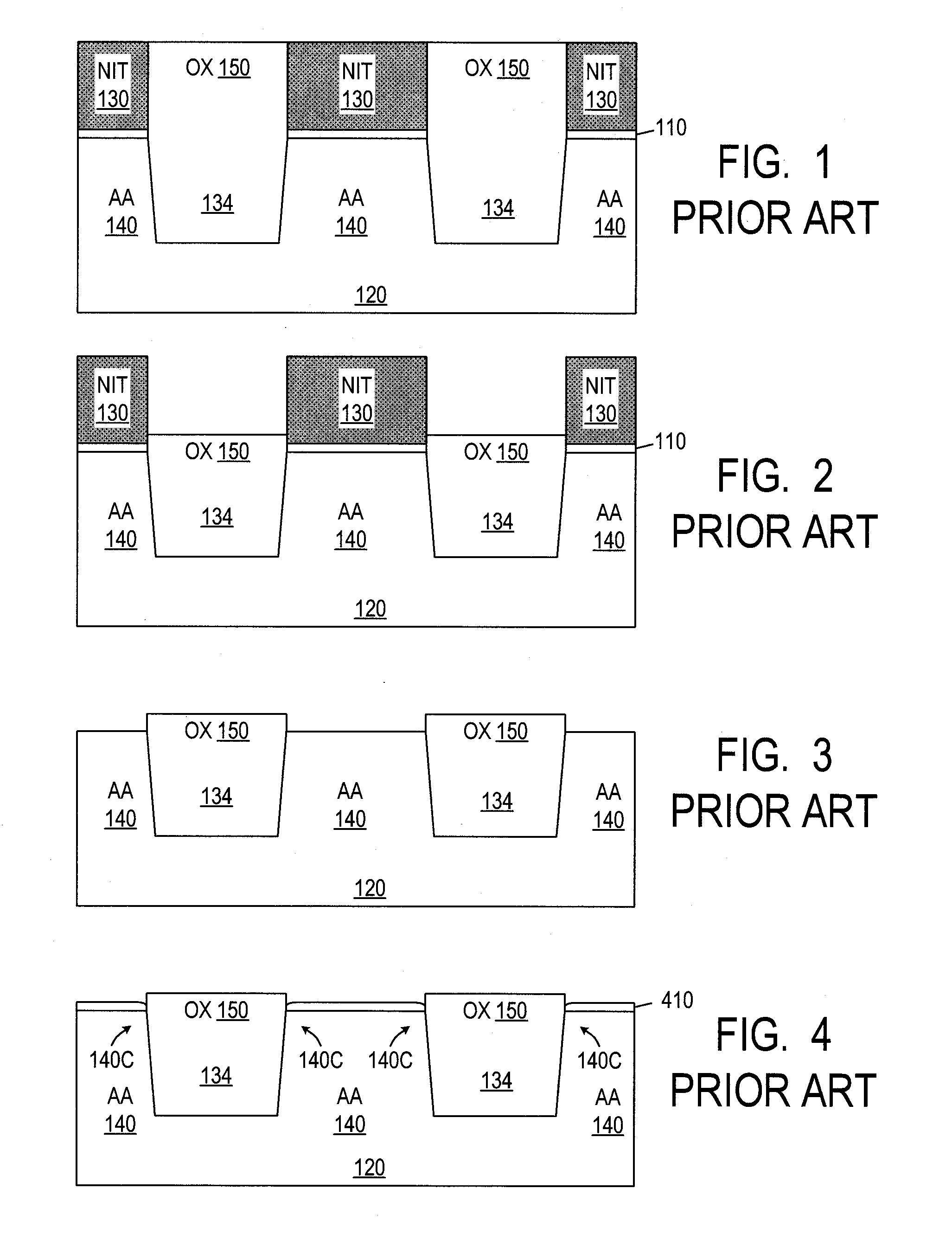
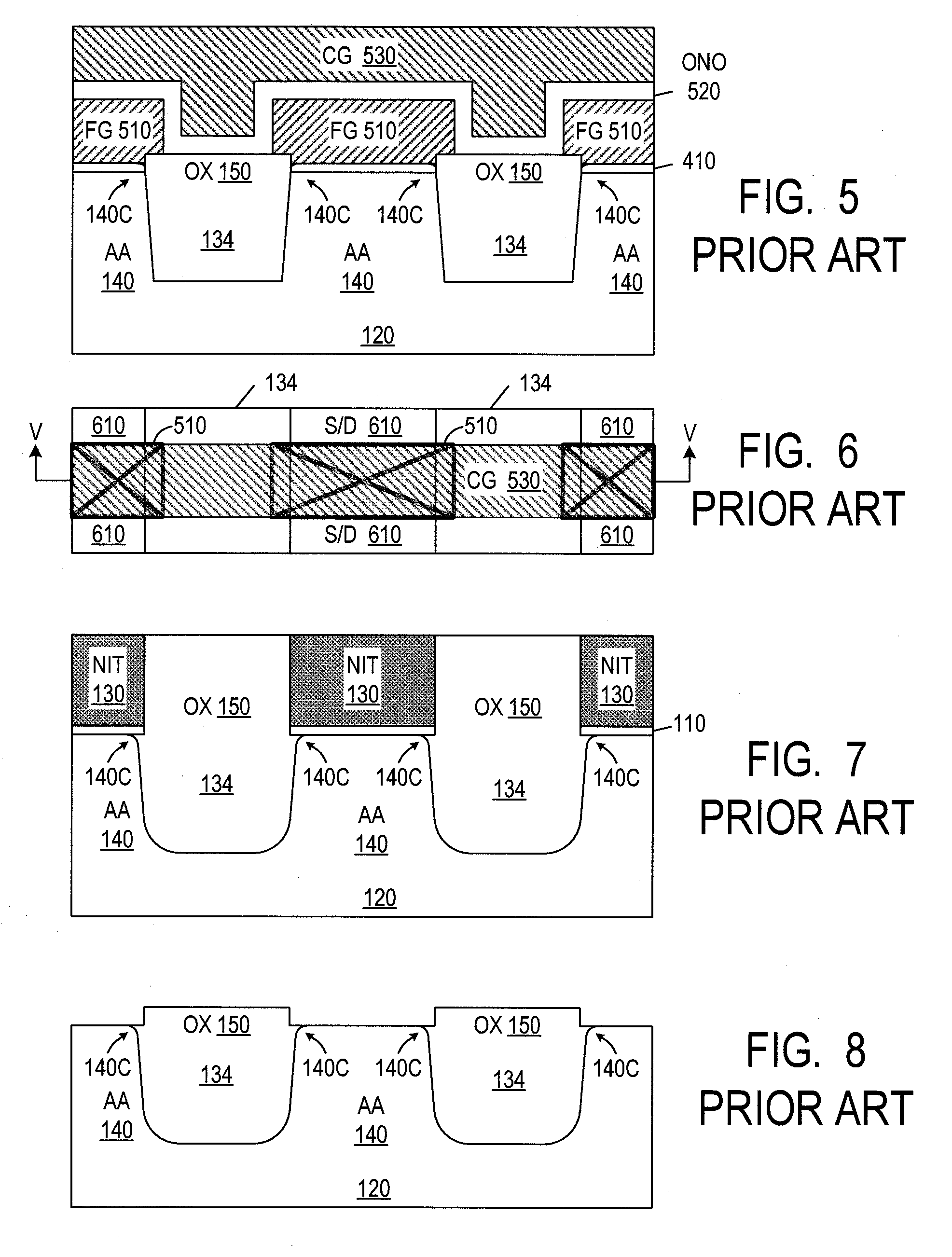
CROSS REFERENCE TO RELATED APPLICATIONS [0001] The present application is a division of U.S. patent application Ser. No. 11 / 174,081 filed on Jun. 30, 2005, incorporated herein by reference.BACKGROUND OF THE INVENTION [0002] The present invention relates to integrated circuits, and more particularly to dielectric formed in trenches in a silicon substrate. Some embodiments are suitable for substrate isolation for integrated circuits. [0003]FIG. 1 illustrates an intermediate structure in a flash memory fabrication process using shallow trench isolation (STI). Silicon dioxide 110 (“pad oxide”) is thermally grown on silicon substrate 120. Silicon nitride 130 is formed on oxide 110 and patterned photolithographically to define substrate isolation trenches 134 to be formed between active areas 140. Oxide 110 and substrate 140 are etched through the openings in nitride 130 to form the isolation trenches. Silicon dioxide 150 is deposited to fill the trenches and cover the wafer. Oxide 150 is...

Claims


Application Information

Patent Timeline
Patent Type & Authority Applications(United States)
IPC IPC(8): H01L21/336H01L29/76
CPCH01L21/28273H01L21/76224H01L21/823481H01L27/115H01L27/11521H01L29/40114H10B69/00H10B41/30
Inventor DONG, ZHONGLEE, TAI-PENG
Owner DONG ZHONG
Learn More