Eureka AIR delivers breakthrough ideas for toughest innovation challenges, trusted by R&D personnel around the world.

Balanced acoustic wave filter device

a filter device and acoustic wave technology, applied in the direction of impedence networks, electrical devices, etc., can solve the problems of inability to achieve satisfactory insertion loss and vswr in a pass band, unbalanced signals are input or output, and components having an unbalanced-to-balance conversion function

Active Publication Date: 2007-06-07
MURATA MFG CO LTD
View PDF12 Cites 13 Cited by
  • Summary
  • Abstract
  • Description
  • Claims
  • Application Information

AI Technical Summary

Benefits of technology

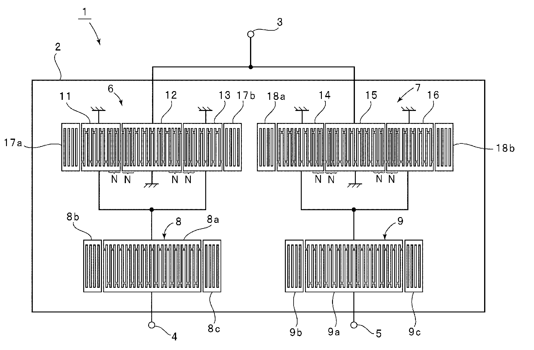
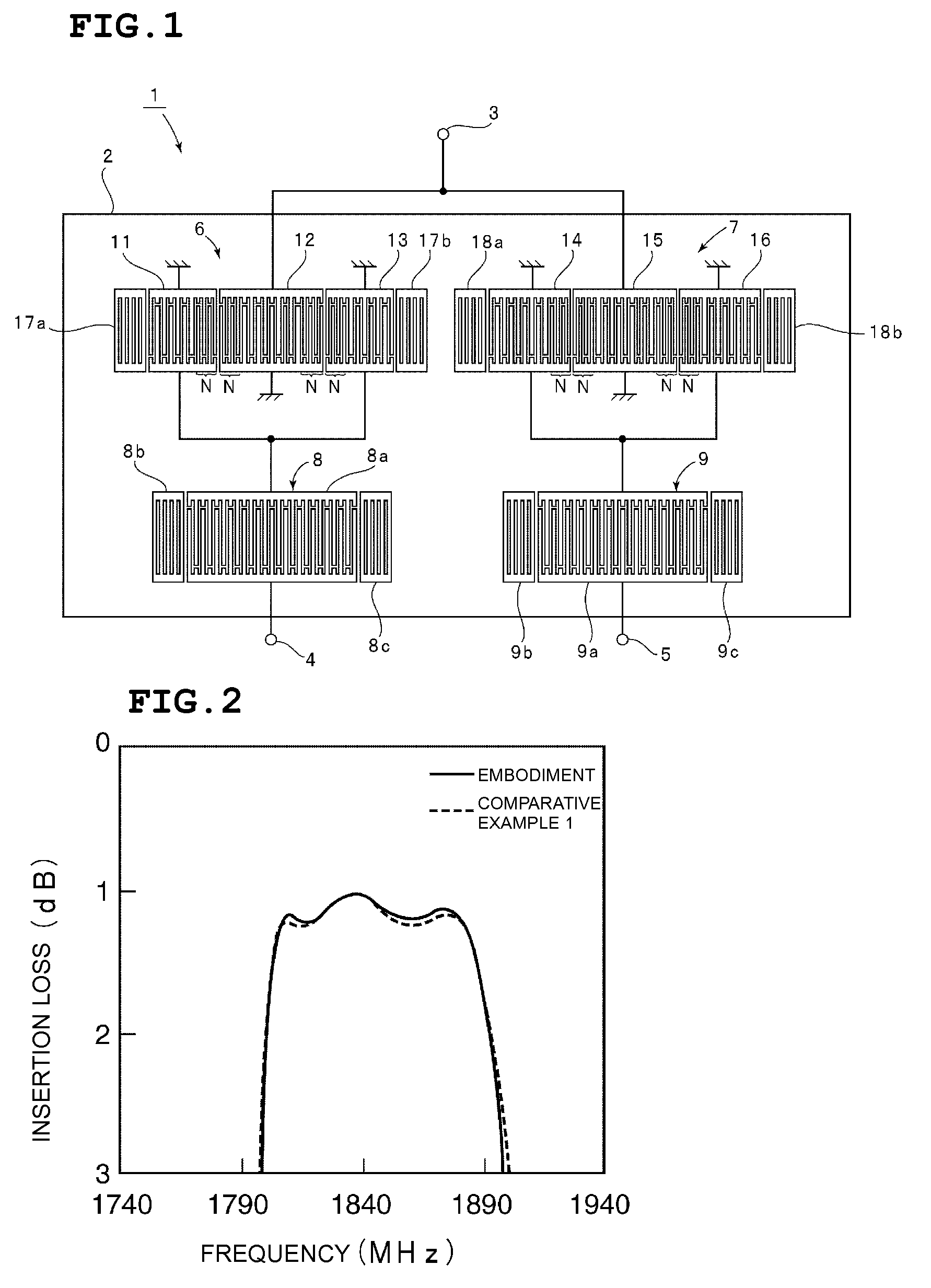
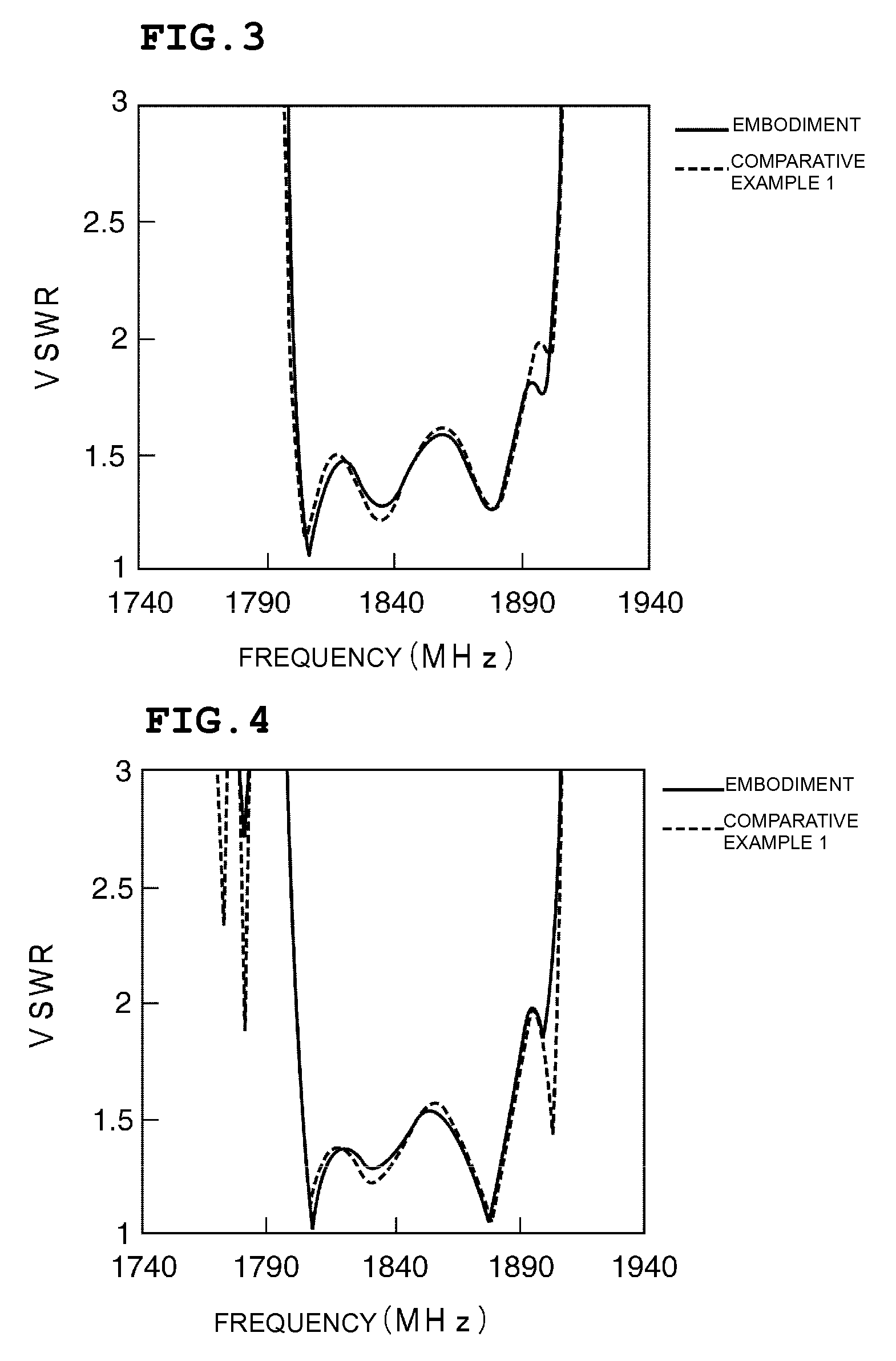
[0095] An advantage of the present invention cannot be achieved by setting the other design parameters to be different, but can be achieved by setting the total numbers of pairs of electrode fingers of the IDTs in the first surface acoustic wave filter section 6 and the second surface acoustic wave filter section 7 to be different from each other. This will be described below.
[0096] In the above-described surface acoustic wave filter device according to Comparative

Problems solved by technology

In this case, unbalanced signals are input or output to an antenna.
Thus, a component having an unbalanced-to-balanced conversion function, that is, a balun, must be inserted between the antenna and the differential amplifier.
However, in the surface acoustic wave filter device 501, satisfactory insertion loss and VSWR in a pass band cannot be achieved.
This causes a difference in bandwidths and deteriorates the VSWR and the insertion loss in the pass band.

Method used


Image

  • Balanced acoustic wave filter device
  • Balanced acoustic wave filter device
  • Balanced acoustic wave filter device

Examples


Embodiment Construction

[0042] The present invention will become apparent from the following descriptions of preferred embodiments of the present invention with reference to the drawings.

[0043]FIG. 1 is a schematic plan view showing a balanced surface acoustic wave filter device according to a first preferred embodiment of the present invention.

[0044] A balanced surface acoustic wave filter device 1 has an electrode structure shown in FIG. 1 provided on a piezoelectric substrate 2.

[0045] In this preferred embodiment, the piezoelectric substrate 2 is preferably a piezoelectric substrate made of 40±5-degree Y-cut, X-propagating LiTaO3. However, the piezoelectric substrate may be made of other types of piezoelectric single crystal or piezoelectric ceramics. In addition, the piezoelectric substrate may be configured such that a piezoelectric thin film is formed on the surface of a piezoelectric material or an insulating material.

[0046] Although the illustrated electrodes are preferably made of aluminum in ...


PUM


Abstract

In a balanced acoustic wave filter device, first and second acoustic wave filter sections that are connected in parallel to an unbalanced terminal are connected to first and second balanced terminals, respectively. The first and second surface acoustic wave filter sections are configured such that the phases of the first and second balanced terminals differ by 180 degrees. The first and second acoustic wave filter sections are longitudinally coupled resonator-type acoustic wave filter sections each including a plurality of IDTs disposed in a direction in which acoustic waves propagate. The total number of pairs of electrode fingers of the IDTs in the second acoustic wave filter section in which the polarities of electrode fingers that are adjacent to each other in an area in which IDTs are adjacent to each other are opposite to each other is greater than the total number of pairs of electrode fingers of the IDTs in the first acoustic wave filter section in which the polarities of electrode fingers that are adjacent to each other in an area in which IDTs are adjacent to each other in the direction in which acoustic waves propagate are equal to each other.

Description

BACKGROUND OF THE INVENTION [0001] 1. Field of the Invention [0002] The present invention relates to balanced acoustic wave filter devices using surface acoustic waves or boundary acoustic waves, and more particularly, to a balanced acoustic wave filter device including first and second longitudinally coupled resonator-type acoustic wave filter sections and having a balanced-to-unbalanced conversion function. [0003] 2. Description of the Related Art [0004] In mobile communication apparatuses, surface acoustic wave filters are often connected as band-pass filters between antennas and differential amplifiers. In this case, unbalanced signals are input or output to an antenna. In contrast, balanced signals are input or output to a differential amplifier. Thus, a component having an unbalanced-to-balanced conversion function, that is, a balun, must be inserted between the antenna and the differential amplifier. If a surface acoustic wave filter having a balanced-to-unbalanced conversion...

Claims


Application Information

Patent Timeline
IPC IPC(8): H03H9/64H01L41/22H01L41/29
CPCH03H9/0071H03H9/0085H03H9/0222H03H9/02748H03H9/14582H03H9/25H03H9/6476H03H9/64H03H9/145
Inventor YATA, MASARU
Owner MURATA MFG CO LTD
Why Eureka
Eureka Blog
Learn More