Sensor for detecting substance in liquid

a technology for detecting substances and liquids, applied in the direction of instruments, suspensions and porous material analysis, chemical/physical/physico-chemical processes, etc., can solve the problem of difficult to reliably detect the detection-target substance in liquid with high precision, and achieve the effect of increasing sensitivity

Active Publication Date: 2009-03-05
MURATA MFG CO LTD
View PDF5 Cites 63 Cited by
  • Summary
  • Abstract
  • Description
  • Claims
  • Application Information

AI Technical Summary

Benefits of technology

[0013]To overcome the problems described above, preferred embodiments of the present invention provide a sensor for detecting a substance in liquid, the sensor being capable of detecting a detection-target substance in liquid with increased sensitivity.
[0015]In the sensor for detecting a substance in liquid according to this preferred embodiment of the present invention, the first and second frequency signals may preferably be selected so as to satisfy dP≧0, for example, where dP=Pr−Ps, wherein Ps is an output signal of the sensing circuit, Pr is an output signal of the reference circuit, and dP is an output signal of the differential circuit. In this case, because the first and second frequency signals are selected so as to satisfy dP≧0, the output of the sensing circuit including the sensing SAW element based on the amplitude of the SAW element caused by the reaction of the detection-target substance in liquid reacts with the reaction film and the addition of mass on the sensing SAW element is relatively low. Accordingly, the magnitude of the output dP from the differential circuit enables the presence or absence and the density of the detection-target substance in liquid to be detected with greater precision and reliability.
[0016]Preferably, a 30° to 40° rotated Y-plate X-propagation lithium tantalate (LiTaO3) substrate may be used as the piezoelectric substrate, for example. This enables the detection-target substance in liquid to be detected with greater sensitivity and reliability.
[0018]In preferred embodiments of the present invention, the sensing SAW element and the reference SAW element are preferably driven by first and second frequency signals, respectively, that are either the same as or different from one another. The differential amplifying circuit outputs a differential output between the output of the sensing circuit including the sensing SAW element based on the amplitude level of the sensing SAW element and the output of the reference circuit including the reference SAW element based on the amplitude of the reference SAW element. Accordingly, the differential output enables the presence or absence or the density of the detection-target substance to be detected based on a decrease in the amplitude level based on a decrease in frequency caused by an increased mass in the sensing SAW element occurring when the detection-target substance is coupled thereto. That is, without an oscillation circuit, the detection-target substance is detected based on the difference in amplitude between the sensing SAW element and the reference SAW element. Accordingly, a driving difference and a decrease in the measurement accuracy do not occur. Thus, the detection-target substance can be detected with greater precision and greater sensitivity.

Problems solved by technology

For this reason, the difference in frequency between the oscillation circuit including the reference SAW element and the oscillation circuit including the sensing SAW element is approximately zero, such that it is difficult to reliably detect the detection-target substance in liquid with high precision.

Method used


Image

  • Sensor for detecting substance in liquid
  • Sensor for detecting substance in liquid
  • Sensor for detecting substance in liquid

Examples


Embodiment Construction

[0025]Preferred embodiments of the present invention will be described below with reference to the drawings.

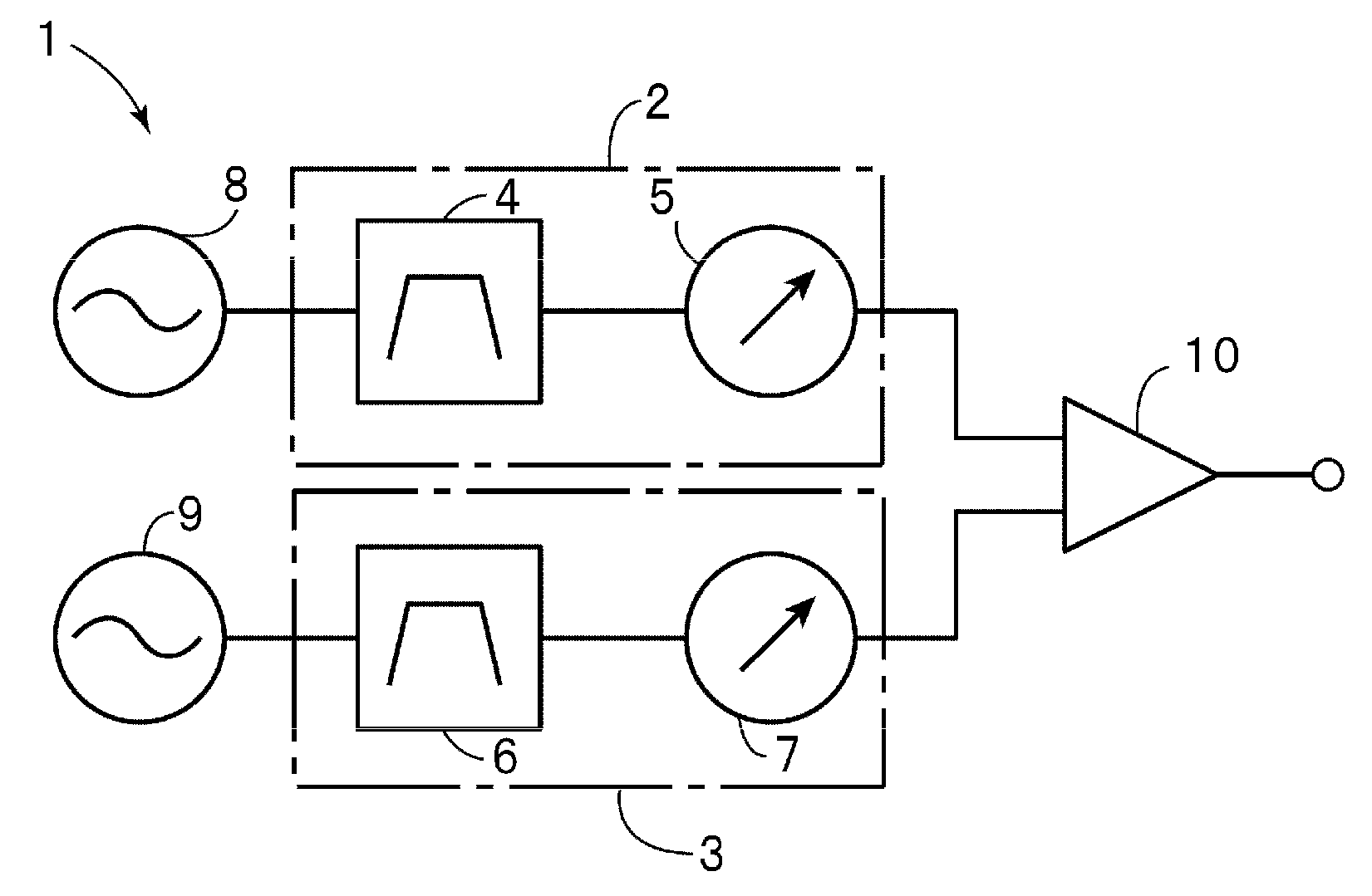
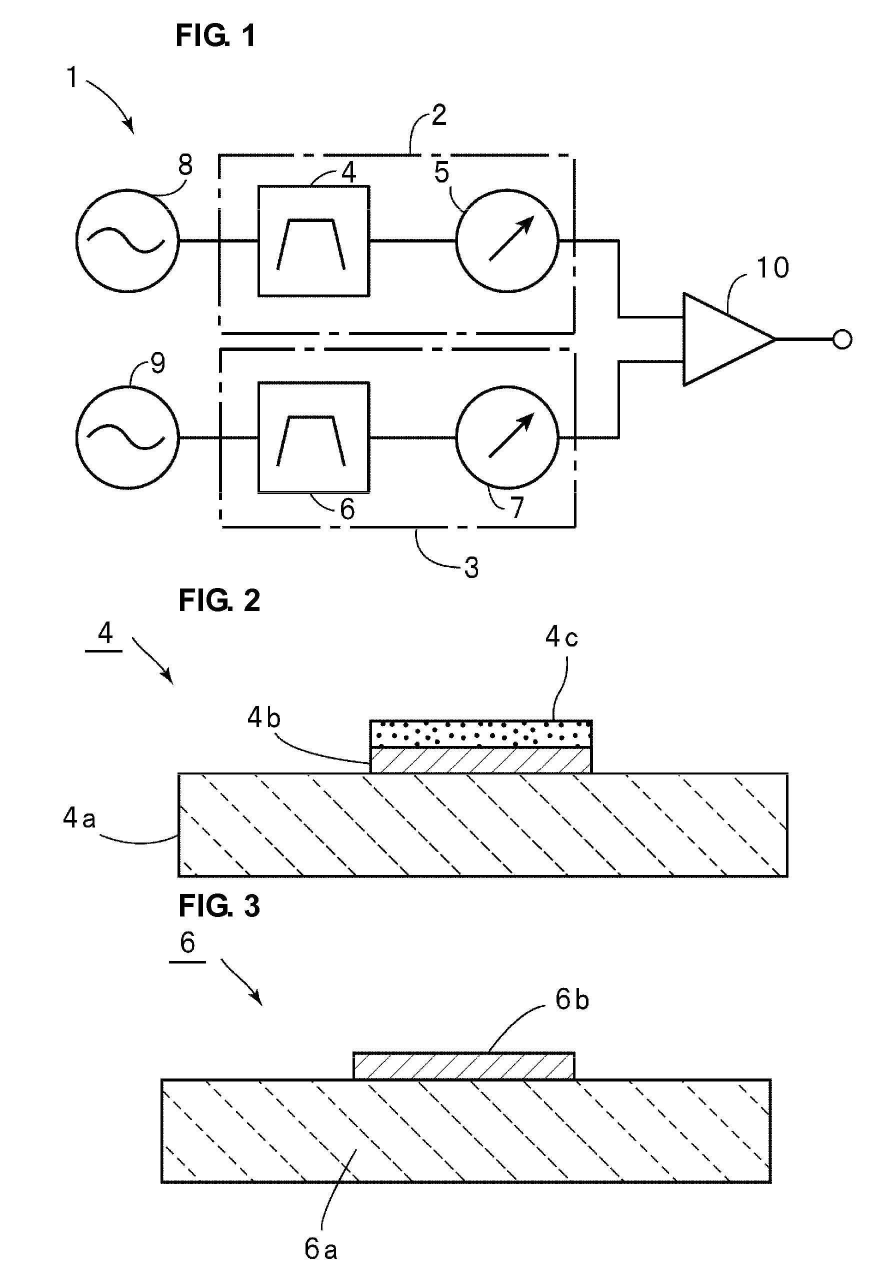
[0026]FIG. 1 is a block diagram that illustrates a circuit configuration of a sensor for detecting a substance in liquid according to a preferred embodiment of the present invention.

[0027]As illustrated in FIG. 1, the sensor 1 for detecting a substance in liquid includes a sensing circuit 2 and a reference circuit 3. The sensing circuit 2 includes a sensing SAW element 4 that is connected to a first output-level detecting circuit 5. The reference circuit 3 includes a reference SAW element 6 that is connected to a second output-level detecting circuit 7.

[0028]Each of the sensing SAW element 4 and the reference SAW element 6 may preferably be defined by a SAW element in which an IDT is provided on a piezoelectric substrate, for example. As schematically illustrated in FIG. 2, in the sensing SAW element 4, an IDT 4b is provided on the upper surface of a piezoelectric substrate 4a...


PUM


Abstract

A sensor for detecting a substance in liquid includes a sensing circuit including a sensing surface acoustic wave (SAW) element in which a reaction film to react with a substance in liquid, a reference circuit including a reference SAW element including an IDT and not including a reaction film, a first signal source driving the sensing circuit, a second signal source driving the reference circuit and being independent of the first signal source, and a differential circuit arranged to output a differential output between an output of the sensing circuit and an output of the reference circuit. The frequency of a first frequency signal output from the first signal source is different from the frequency of a second frequency signal output from the second signal source, thereby making a driving frequency for the sensing SAW element and a driving frequency for the reference SAW element substantially the same as or different from one another.

Description

BACKGROUND OF THE INVENTION[0001]1. Field of the Invention[0002]The present invention relates to sensors for detecting a substance in liquid using a surface acoustic wave element (SAW element), and more specifically, to a sensor for detecting a substance in liquid, the sensor including a sensing SAW element and a reference SAW element.[0003]2. Description of the Related Art[0004]Various sensors have been developed for detecting a substance (detection-target substance) in liquid, for example, a protein. For example, WO2006 / 027893A1 discloses a sensor for detecting a substance in liquid using a surface acoustic wave element. FIG. 5A is a plan view for describing a sensor for detecting a substance in liquid described in WO2006 / 027893A1, and FIG. 5B is a front cross-sectional view that illustrates a main portion thereof.[0005]A sensor 101 for detecting a substance in liquid includes a base substrate 102. The base substrate 102 includes an upper surface 102a in which recesses 102c and 10...

Claims


Application Information

Patent Timeline
Patent Type & Authority Applications(United States)
IPC IPC(8): B01J19/00
CPCG01N29/022G01N2291/0423G01N2291/0256G01N2291/0255
Inventor OKAGUCHI, KENJIROHADA, TAKUOKADOTA, MICHIO
Owner MURATA MFG CO LTD
Why Eureka
Try Eureka