
Finned helicoidal heat exchanger

a heat exchanger and helical coil technology, applied in the field of heat exchangers, can solve the problems of reducing the overall heat exchange capability of the coil, limiting the types of fin materials that can be used, and excessive pressure drop in the first fluid, so as to enhance the exchange of thermal energy.

Inactive Publication Date: 2007-06-07
FAKHERI AHMAD
View PDF22 Cites 44 Cited by
  • Summary
  • Abstract
  • Description
  • Claims
  • Application Information

AI Technical Summary

Benefits of technology

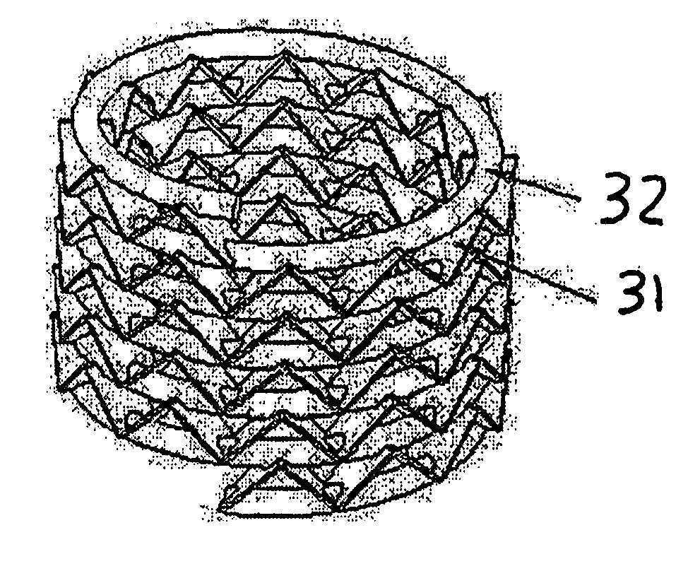
[0011] It is in view of the above problems that the present invention was developed. The invention is a heat exchanger having a plurality of heat transfer tubes arranged substantially in the shape of a helicoidal tube with the individual coils running parallel to one another in a spiral pattern. A plurality of fins are secured to the external surfaces of the heat transfer tubes and extend away therefrom. The first working fluid flows inside the heat transfer tubes, and the second working fluid, typically air, flows through the passages between the adjacent fins and tubes. To further enhance the exchange of thermal energy between the fluids, a blower may be placed inside the coil cavity or around the coil, with blower's blades being parallel to the central coil axis.
[0012] The invention incorporates characteristics of high fin density, close coil spacing, and non-uniform fin size. The attachment of the fins to at least two adjacent loops not only enhances the rate of heat transfer, but also provides for enhanced structural strength that allows the use of this design for applications where the first heat exchanging fluid is at elevated pressures. These characteristics and the absence of 180 degree bends result in a significantly more compact heat exchanger having superior heat transfer characteristics.

Problems solved by technology

The return bends force the first fluid to turn 180 degrees in each pass thereby causing an excessive pressure drop in the first fluid.
This non-uniform air velocity through different portions of the coil often creates a variety of operational problems and inefficiencies in which the coil is incorporated, leading to a lowering the overall heat exchange capability of the coil.
They also limit the types of fin material that can be used.
High pressure applications also are problematic because in known heat exchangers the fins do not strengthen the heat exchanger and, thus, service life is adversely affected.

Method used


Image

  • Finned helicoidal heat exchanger
  • Finned helicoidal heat exchanger
  • Finned helicoidal heat exchanger

Examples


Embodiment Construction

[0025] The following description of the preferred embodiment(s) is merely exemplary in nature and is in no way intended to limit the invention, its application, or uses.

[0026] The embodiments disclosed below are not intended to be exhaustive or limit the invention to the precise forms disclosed below. Rather, the embodiments are chosen and described so that others skilled in the art may utilize their teachings.

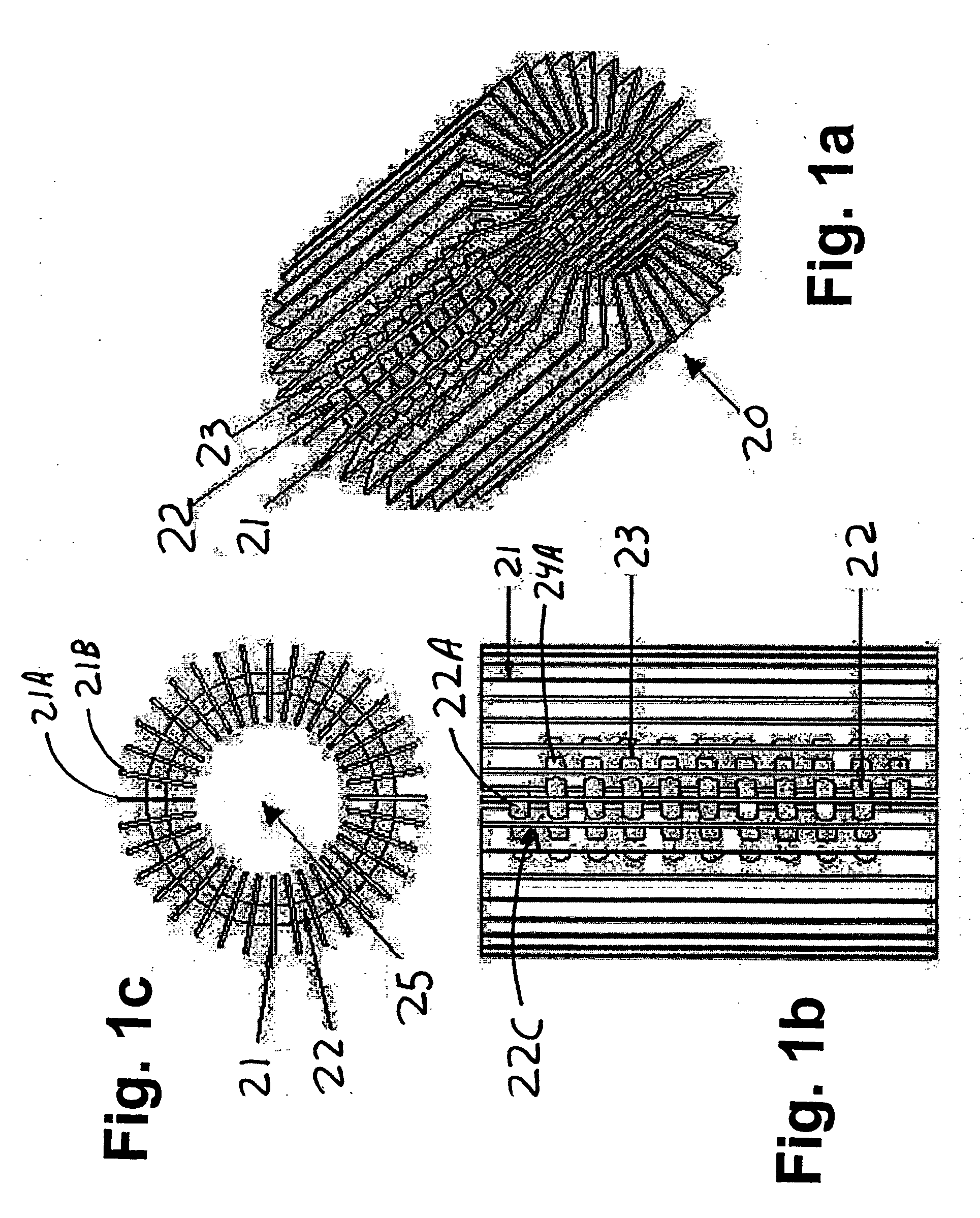
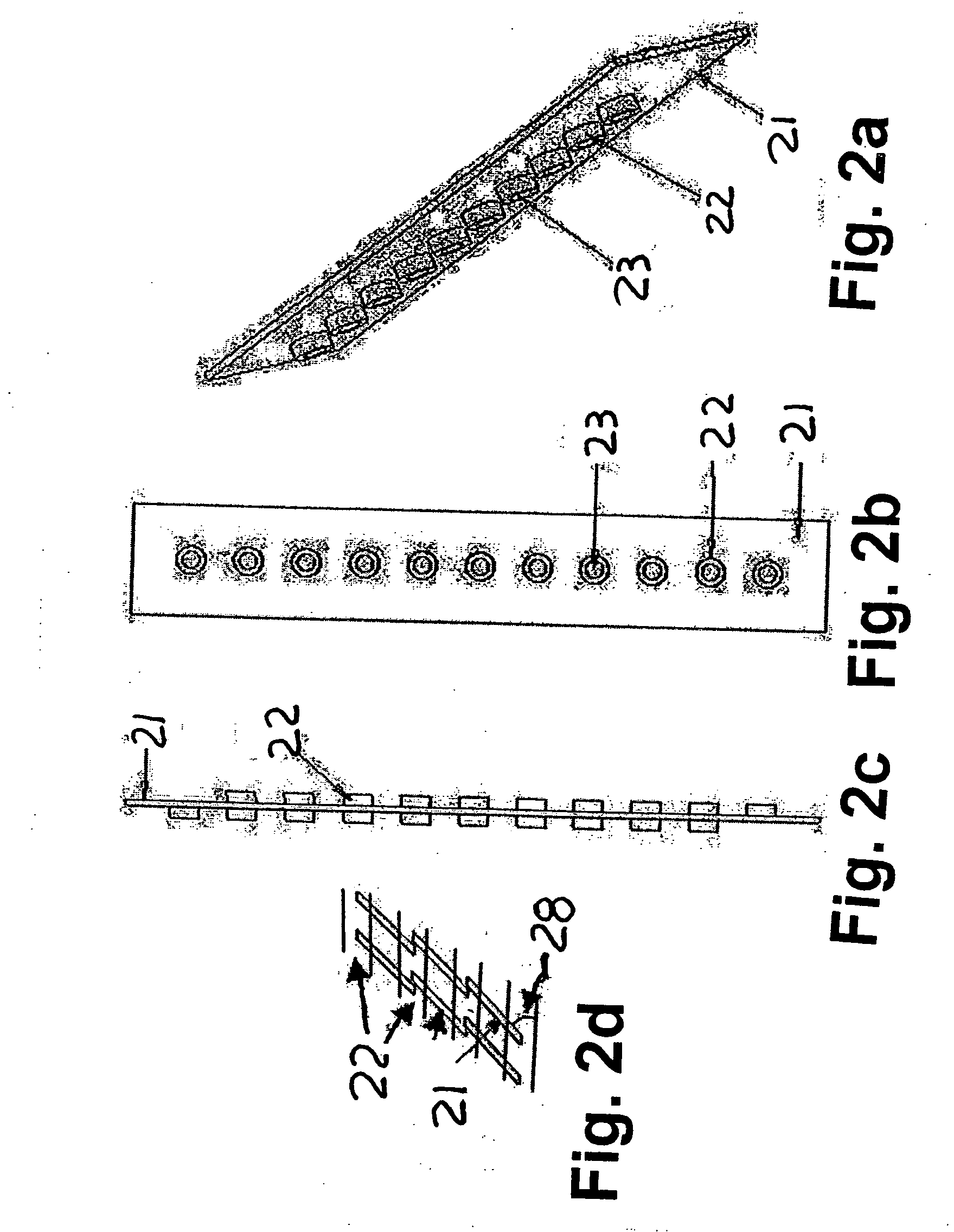
[0027] Referring to the accompanying drawings in which like reference numbers indicate like elements, FIGS 1a-1c illustrate a finned helicoidal heat exchanger 20. The helicoidal heat exchanger 20 includes a heat transfer tube 22 arranged substantially in the shape of a continuous helicoidal tube. The helicoidal heat exchanger 20 also includes a fin 21 secured to the external surfaces of the heat transfer tube 22. FIGS 1a-1c illustrate an embodiment having a plurality of evenly spaced fins 21A, 21B secured to the external surfaces of the heat transfer tube 22 and extending ou...


PUM


Abstract

Heat exchanger having a plurality of heat transfer tubes arranged substantially in the shape of a helicoidal tube with the individual coils running parallel to one another, and a plurality of fins secured to the external surfaces of the heat transfer tubes and arranged perpendicular to the tube to extend outwardly therefrom. The first working fluid flows inside the heat transfer tubes, and air flows through a passage defined between the adjacent fins and at right angles to the axis of each heat transfer tube. The blower is placed co-axial with the helicoid's axis to further enhance the heat exchange.

Description

CROSS-REFERENCE TO RELATED APPLICATIONS [0001] This application is a divisional of United States Patent Application No. 10 / 748,636 filed on Dec. 30, 2003.STATEMENT REGARDING FEDERALLY SPONSORED RESEARCH [0002] Not Applicable. APPENDIX [0003] Not Applicable. BACKGROUND OF THE INVENTION [0004] 1. Field of The Invention [0005] The present invention relates generally to the field of heat exchangers and, more particularly, to a heat exchanger having helical coils whose performance is improved by the addition of fins. [0006] 2. Related Art [0007] Heat exchangers are used to transfer heat between fluids. Many different designs accomplish this, invariably by relying on the basic thermodynamic principle that heat is transferred from a warmer body to a cooler one. One of the more commonly used types of heat exchangers is a fin and tube heat exchanger, such as the evaporator or condenser of a common air conditioner. Separate fin strips are arranged in an array with holes in each to receive per...

Claims


Application Information

Patent Timeline
IPC IPC(8): F28D1/02
CPCF28D1/024F28D1/0472F28D1/0473F28F1/022F28F1/126F28F1/32F28F1/325
Inventor FAKHERI, AHMAD
Owner FAKHERI AHMAD
Learn More