Thin prestressed concrete panel and apparatus for making the same

Inactive Publication Date: 2007-06-07
BLOUNT BRIAN M
View PDF23 Cites 12 Cited by
  • Summary
  • Abstract
  • Description
  • Claims
  • Application Information

AI Technical Summary

Benefits of technology

[0005] In accordance with the invention, concrete panels are prepared by casting panels of about 1.5 inch thickness or less, which contain prestressed tendons. The tendons are oppositely positioned between the mid-plane of the panel and each of the opposite faces and may be spaced either equidistantly or at different distances from the adjacent face, in spaced grids. The positioning of opposing tendons between the mid-plane and the opposite faces increases panel resilience and will effect return of a panel to its original shape after being flexurally deformed by loads imposed normal to its faces, such return being effected even if a crack has developed in the tension face of the panel. OBJECTS OF THE INVENTION
[0006] It is, accordingly, an object of this invention to provide a prestressed concrete panel that is thin, light, durable and resilient.
[0007] Another object of the invention is to provide a prestressed concrete panel that may be field cut and easily installed on a structure.
[0008] Still another object of the invention is to provide an improved apparatus for casting prestressed concrete panels at a reduced cost.

Problems solved by technology

Exterior cladding of a building is subjected to attacks from climatic conditions such as freeze-thaw cycles, moisture intrusion, ultra-violet rays, wind and seismic loading and sometimes vibration from traffic and other sources, amongst other things.
However, precast concrete cladding, as used heretofore, is provided typically in heavy elements and its use has been limited to reinforced concrete or steel frame structures due to the load that it imposes on a building.
Consequently, a building designed to carry the lateral and gravity loads imposed by the heavy concrete skin system is costly.
Moreover, existing concrete panel systems are susceptible to permanent deformation from perpendicularly applied loads that create surface cracks in the tension face of the panel.

Method used


Image

  • Thin prestressed concrete panel and apparatus for making the same
  • Thin prestressed concrete panel and apparatus for making the same
  • Thin prestressed concrete panel and apparatus for making the same

Examples


Embodiment Construction

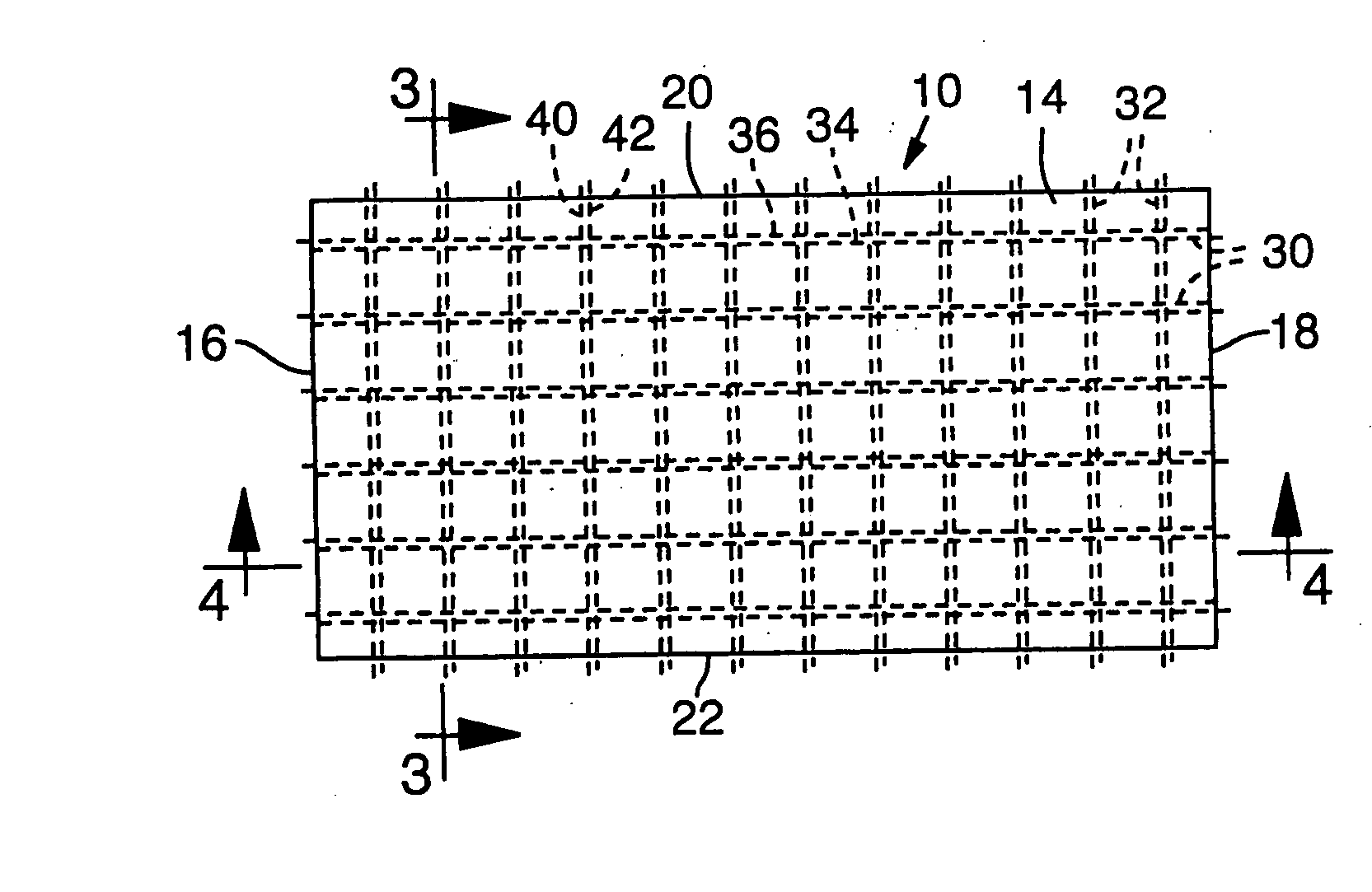
[0027] Referring first to FIGS. 1-4, there is therein illustrated a preferred embodiment of the invention comprising a thin prestressed, reinforced concrete panel 10, which may be, for example, approximately 50 inches in length, 25 inches in width and have a ⅝ inch thickness. This size is only illustrative since the panel may be made in a wide variety of sizes. A thin panel as used herein refers to a panel with a maximum thickness of approximately 1.5 inches.

[0028] The illustrated panel 10 is formed with an exposed face 12 and an opposite back face 14 each of which faces are flat and parallel to one another. Alternatively, the exposed face 12 may be textured rather than flat to achieve a desired architectural appearance on the panel. Panel 10 is shown as formed with a pair of opposite end faces, or edges, 16, 18, and a pair of opposite side faces, or edges, 20, 22. In the illustrated embodiment the side and end faces are beveled such that the back face 14 is of larger dimensions in...


PUM

PropertyMeasurementUnit
Distanceaaaaaaaaaa
Massaaaaaaaaaa
Fractionaaaaaaaaaa

Abstract

A thin, prestressed concrete panel, having a thickness of about one and one-half inch thickness or less, and apparatus for making the same is disclosed. Pairs of prestressed tendons extend between the side and end portions of the panel. The tendons of each pair are positioned on each side of the mid-plane of the panel and spaced from such mid-plane so as to increase panel strength and prevent warping of the panel. A molding apparatus for casting the panel comprises a bottom plate, a pair of opposite side portions, and a pair of opposite end portions. Slots are defined in the side and end portions through which tendons are inserted prior to pouring concrete in the mold. Tensioning means are provided for prestressing the tendons in the longitudinal and lateral directions of the panel.

Description

[0001] This is a continuation-in-part of U.S. patent application Ser. No. 09 / 684,874, filed Oct. 6, 2000, which is incorporated herein by reference.THE FIELD OF INVENTION [0002] The present invention relates to the construction and manufacture of thin prestressed concrete panels useful for architectural cladding of buildings and other purposes. BACKGROUND OF THE INVENTION [0003] Exterior cladding of a building is subjected to attacks from climatic conditions such as freeze-thaw cycles, moisture intrusion, ultra-violet rays, wind and seismic loading and sometimes vibration from traffic and other sources, amongst other things. [0004] Precast concrete cladding systems have been used extensively on commercial buildings because of their durability and architectural appeal. However, precast concrete cladding, as used heretofore, is provided typically in heavy elements and its use has been limited to reinforced concrete or steel frame structures due to the load that it imposes on a buildin...

Claims


Application Information

Patent Timeline
IPC IPC(8): E04C5/08
CPCB28B23/043E04C5/085E04F13/0835
Inventor BLOUNT, BRIAN M.
Owner BLOUNT BRIAN M
Why Eureka
Try Eureka