
Method and device for removal of radiocontrast media from blood

a radiocontrast media and blood technology, applied in the field of contrast nephropathy, can solve the problems of cs to collapse around the catheter, introduce some new limitations, and impede coronary blood flow leading to angina/ischemia, so as to reduce the hct, accurately detect the presence of contrast, and the contrast conductivity is higher

Active Publication Date: 2007-05-31
GAMBRO LUNDIA AB
View PDF19 Cites 26 Cited by
  • Summary
  • Abstract
  • Description
  • Claims
  • Application Information

AI Technical Summary

Benefits of technology

This system effectively removes radiocontrast agents from the bloodstream, reducing the risk of contrast nephropathy by maintaining physiological blood flow and minimizing the duration and concentration of contrast exposure to the kidneys, thus enhancing the safety and efficacy of procedures like cardiac catheterization.

Problems solved by technology

An alternative solution was proposed that eliminates all of the above shortcomings but introduces some new limitations.
Excessively high CS pressure can impede coronary blood flow leading to angina / ischemia.
Excessively low CS pressure can cause CS to collapse around the catheter.

Method used


Image

  • Method and device for removal of radiocontrast media from blood
  • Method and device for removal of radiocontrast media from blood
  • Method and device for removal of radiocontrast media from blood

Examples


second embodiment

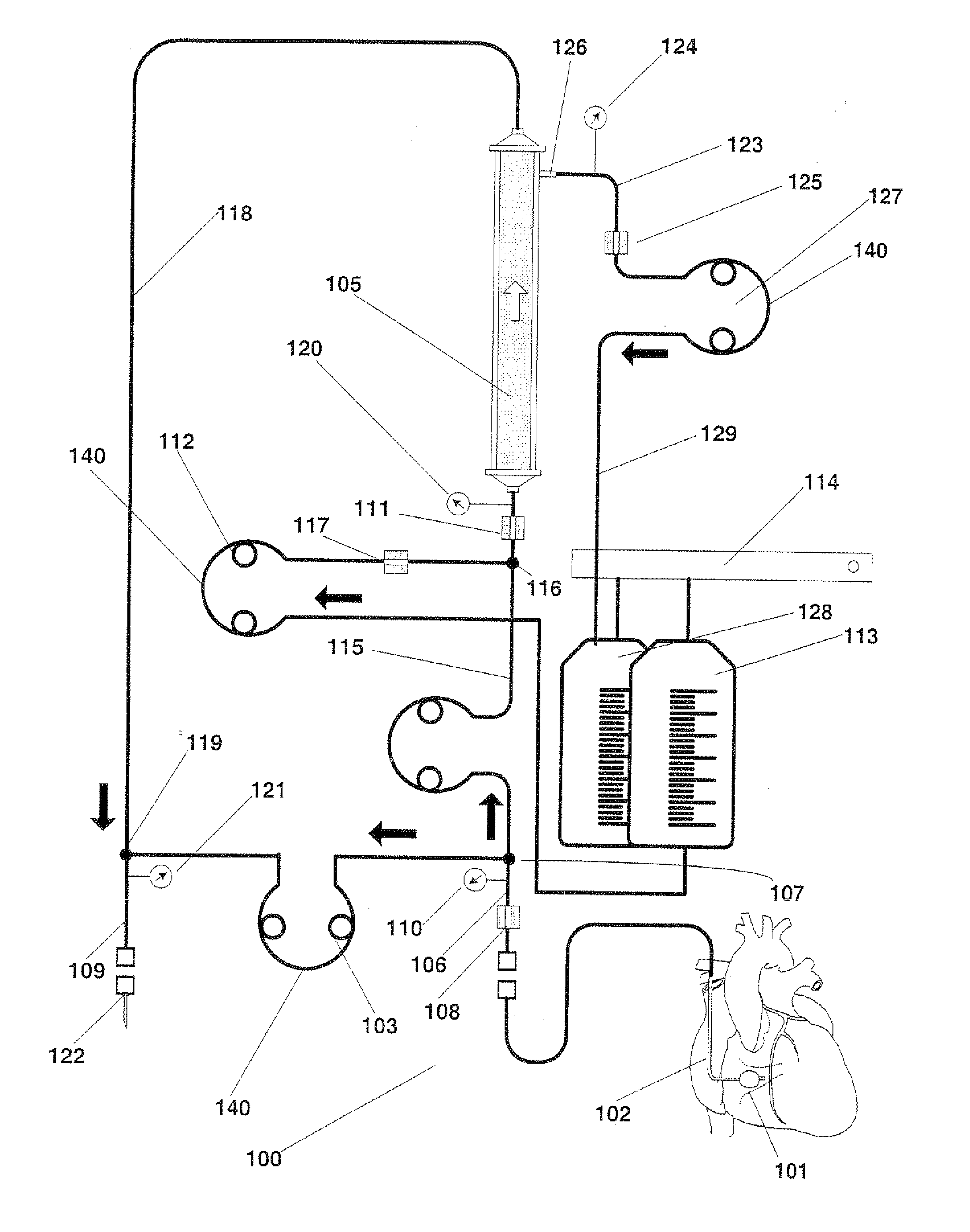
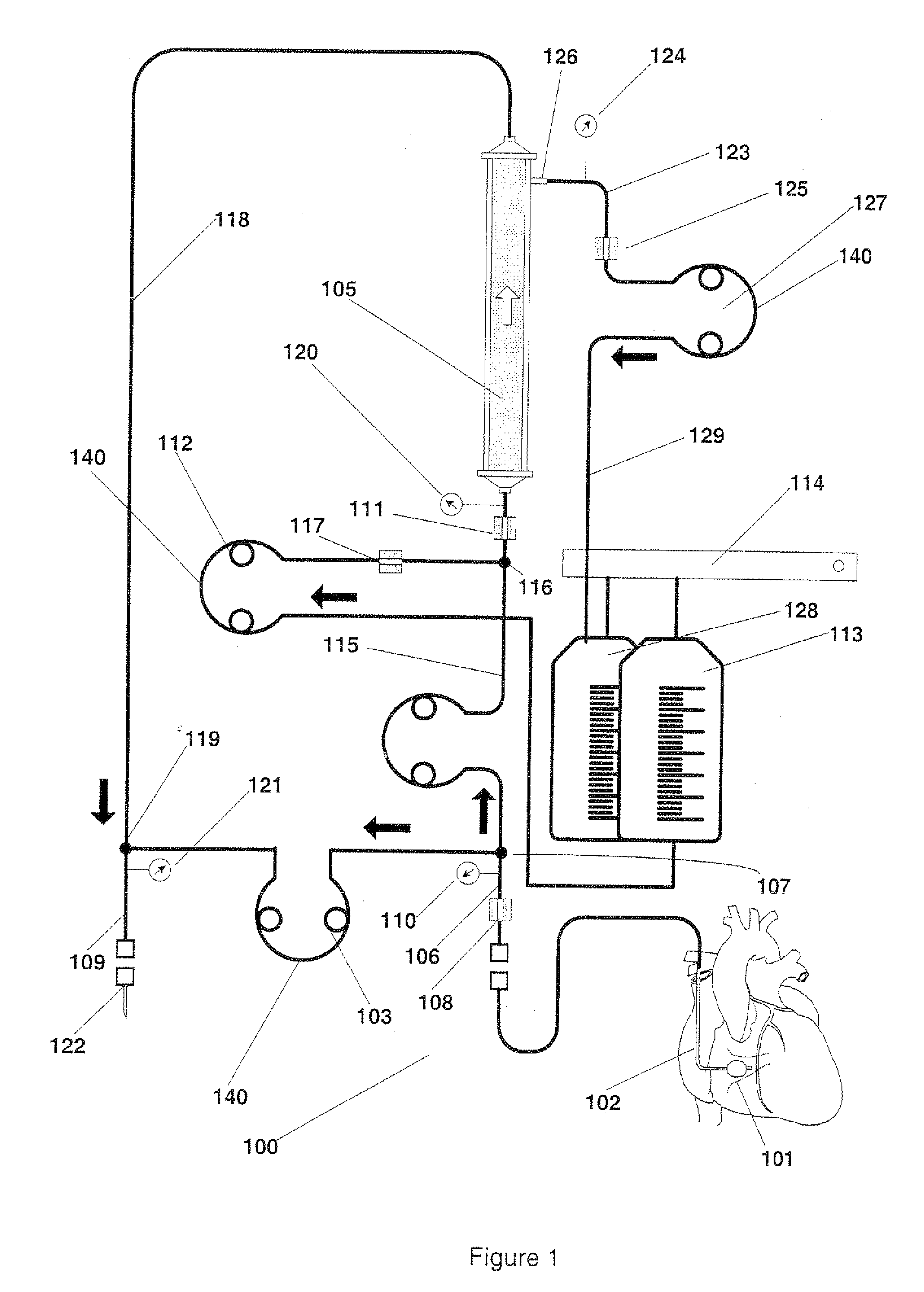
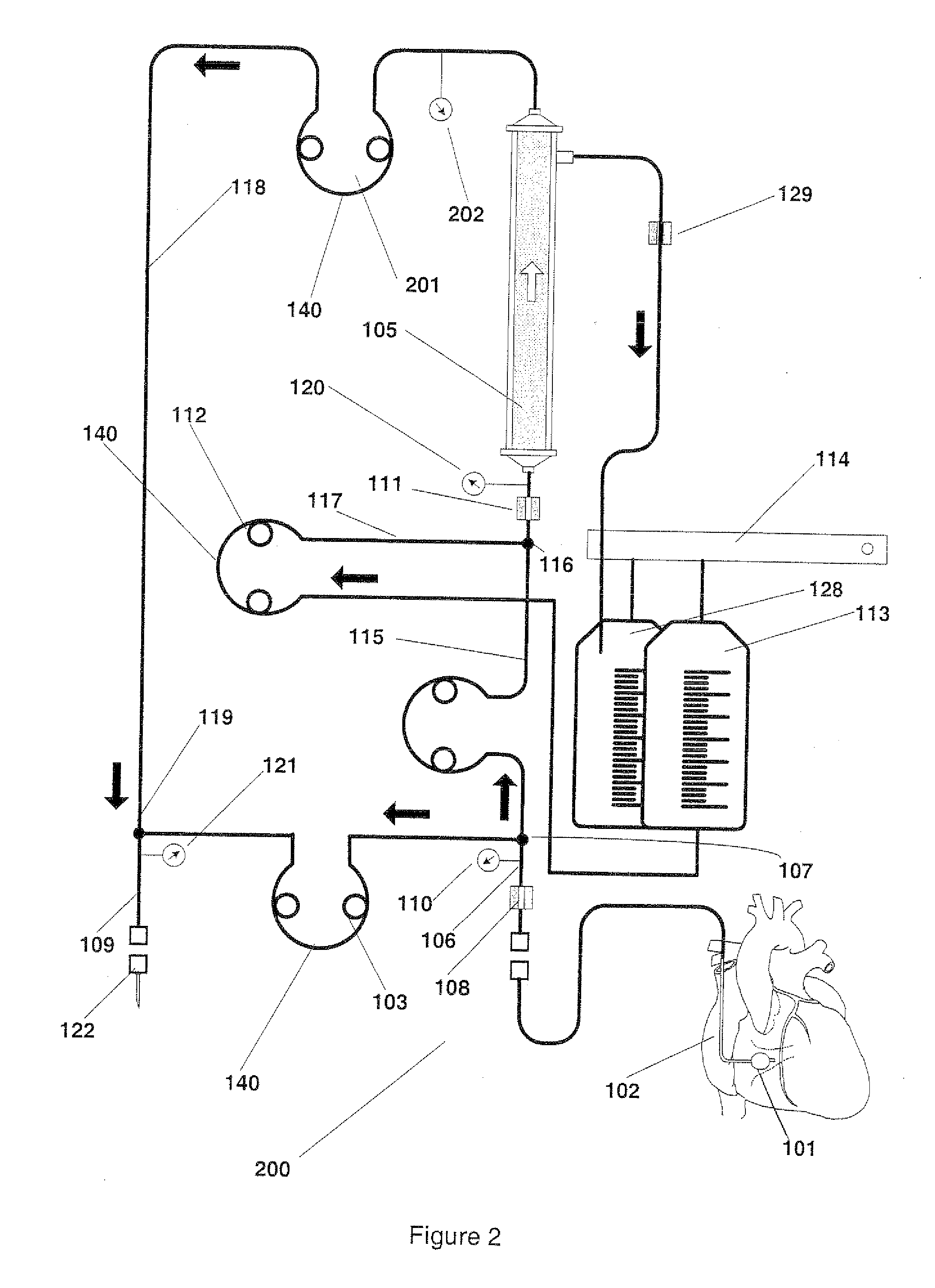
[0113]FIG. 2 shows a second embodiment that is a slight modification to FIG. 1. In this design the ultrafiltrate pump 127 has been removed and replaced with a post filter blood pump 201. Ultrafiltration is achieved by creating a difference in blood flow between prefilter blood pump and post filter blood pump. This variation is provided to show that variations of pump configurations are possible and are within the scope of this invention. A post filter pressure transducer 202 may also be placed at the outlet of the filter 105 to measure post filter pressure.

third embodiment

[0114]FIG. 16 shows a third embodiment in which the contrast removal from the blood using the filter 105 is performed in a batch process. The blood is first withdrawn and collected in a bag 180. It may also be filtered during this process but since the blood flow will be as high as 200 ml / min the infusion duration for blood into the filter and collection bag will be as short as 6 to 12 seconds (20 to 40 ml). The entrained blood (which contains of contrast) later pumped back through the filter by the reversal of the prefilter blood pump and is infused into the patient after contrast is removed. Blood is pumped into the blood collection bag post filter until the bolus of contrast has been entrained plus an additional 20 ml of non contrast diluted blood to ensure that the contrast is entrained within the filter and bag only. The prefilter blood pump is stopped and the bypass blood pump is restarted switching the control of the CS physiological blood flow from the prefilter blood pump t...


PUM


Abstract

An extracorporeal blood circuit including: a withdrawal conduit connectable to a coronary withdrawal catheter; a withdrawal pump connectable to the withdrawal conduit, wherein a pumping rate of the withdrawal pump determines a blood withdrawal rate from the coronary withdrawal catheter; a filter having an input connected to the withdrawal conduit and a blood output connected to an infusion conduit and a filtrate output connected to a filtrate conduit; a filtrate measurement device to determine an amount of filtrate removed from the blood in the filter; a fluid supplementation conduit providing a blood replacement fluid to at least one of the withdrawal conduit, filter and infusion conduit; a supplementation pump connectable to the fluid supplementation conduit, wherein a pumping rate of the supplementation pump determines a rate at which the blood replacement fluid flows into the blood flowing through the blood circuit, and a controller regulating the pumping rate of the supplementation pump such that the rate of the blood replacement fluid provides an amount of blood replacement fluid to the at least one of the withdrawal conduit, filter and infusion conduit so as to substantially match the amount of filtrate removed.

Description

RELATED APPLICATION [0001] This is a divisional application of U.S. patent application Ser. No. 10 / 653,100 (U.S. Pat. No. 7,163,520) filed Sep. 3, 2003, which is a continuation-in-part (CIP) application of U.S. patent application Ser. No. 10 / 606,365, filed Jun. 26, 2003, and claims priority, under 35 U.S.C. §119(e), to U.S. Provisional Application Ser. No. 60 / 391,413 filed Jun. 26, 2002, the entirety of each of these applications is incorporated herein by reference.BACKGROUND OF THE INVENTION Contrast Nephropathy—the Clinical Problem [0002] With the increasing use of radiographic contrast media in diagnostic and interventional procedures, contrast-induced nephropathy (CN) has become an important cause of acute renal impairment. While CN rarely (less than 1% of cases) results in permanent renal failure, CN in any form, results in a significantly increased overall cost to the hospital from prolonged admissions to observe and / or treat while awaiting the return of the patient's pre-CN ...

Claims


Application Information

Patent Timeline
Patent Type & Authority Applications(United States)
IPC IPC(8): A61M31/00A61M1/34A61M1/36B01D61/14B01D61/22
CPCA61M1/342A61M1/3621B01D61/145A61M1/34A61M1/3431A61M1/3613A61M1/3615B01D61/22A61M1/3441A61M1/3451A61M1/36A61M2205/15A61M2205/3331A61M1/341A61M1/3616
Inventor BERNARD, STEVEN J.O'MAHONY, JOHN J.HALPERT, ANDREW V.GELFAND, MARKLEVIN, HOWARD R.
Owner GAMBRO LUNDIA AB
Learn More