Frequency-weighted vehicle suspension control

a vehicle suspension and frequency-weighted technology, applied in the field of frequency-weighted vehicle suspension control, can solve the problems of poor normal ride comfort, conflicting dual objectives of maximizing ride comfort and handling, and vehicle handling suffering

Inactive Publication Date: 2007-05-24
DELPHI TECH INC
View PDF3 Cites 13 Cited by
  • Summary
  • Abstract
  • Description
  • Claims
  • Application Information

AI Technical Summary

Benefits of technology

[0007] The present invention provides a way to synthesize a state-feedback gain matrix for a vehicle suspension system including continuously variable semi-active dampers. Existing sensors and/or estimation schemes are utilized to provide data to the controller concerning the vehicle states. A set of frequency-weighted metrics are first quantified and used as part of a full car 7 degree of freedom vehicle model to construct a constrained multi-objective optimization problem. Using commercially available sof

Problems solved by technology

Although active and semi-active suspension systems have been somewhat effective, the dual objectives of maximizing ride comfort and handling are often in conflict.
If the control scheme is configured to maximize ride comfort, vehicle handling suffers.
Conversely, if the control scheme is configured to optimize vehicle handling, poor ride comfort normally results.
Designing / synthesizing a controller in an effort to achieve an optimum balance between ride and handling has involved adjusting a large number of control parameters or gains in an ad-hoc, time-consuming manner.
Due to the large number of variables, it is extremely difficult, if not impossible, to achieve an optimum trade-off between ride comfort and vehicle handling.
Several integrated body and wheel control arrangements for both active and semi-active suspension systems have been proposed, but such systems have been difficult, if not impossible, to implement given current computational limitations of cost-constrained controllers in a mass-production environment.
In general, these higher-order dynamic compensators are computationally intensive to implement.
Although quarter-car based controllers are of lower-order and therefore relatively easy to implement, this type of closed-loop system typically lacks the flexibility required to tune and alter heave, roll and pitch modes independently.
Although these papers demonstrate the potential effectiveness of the synthesis procedure on half and full-car models respectively, the resulting controllers were of higher-order which are difficult to implement on cost-limited micro controllers utilized in existing vehicles.

Method used


Image

  • Frequency-weighted vehicle suspension control
  • Frequency-weighted vehicle suspension control
  • Frequency-weighted vehicle suspension control

Examples


example

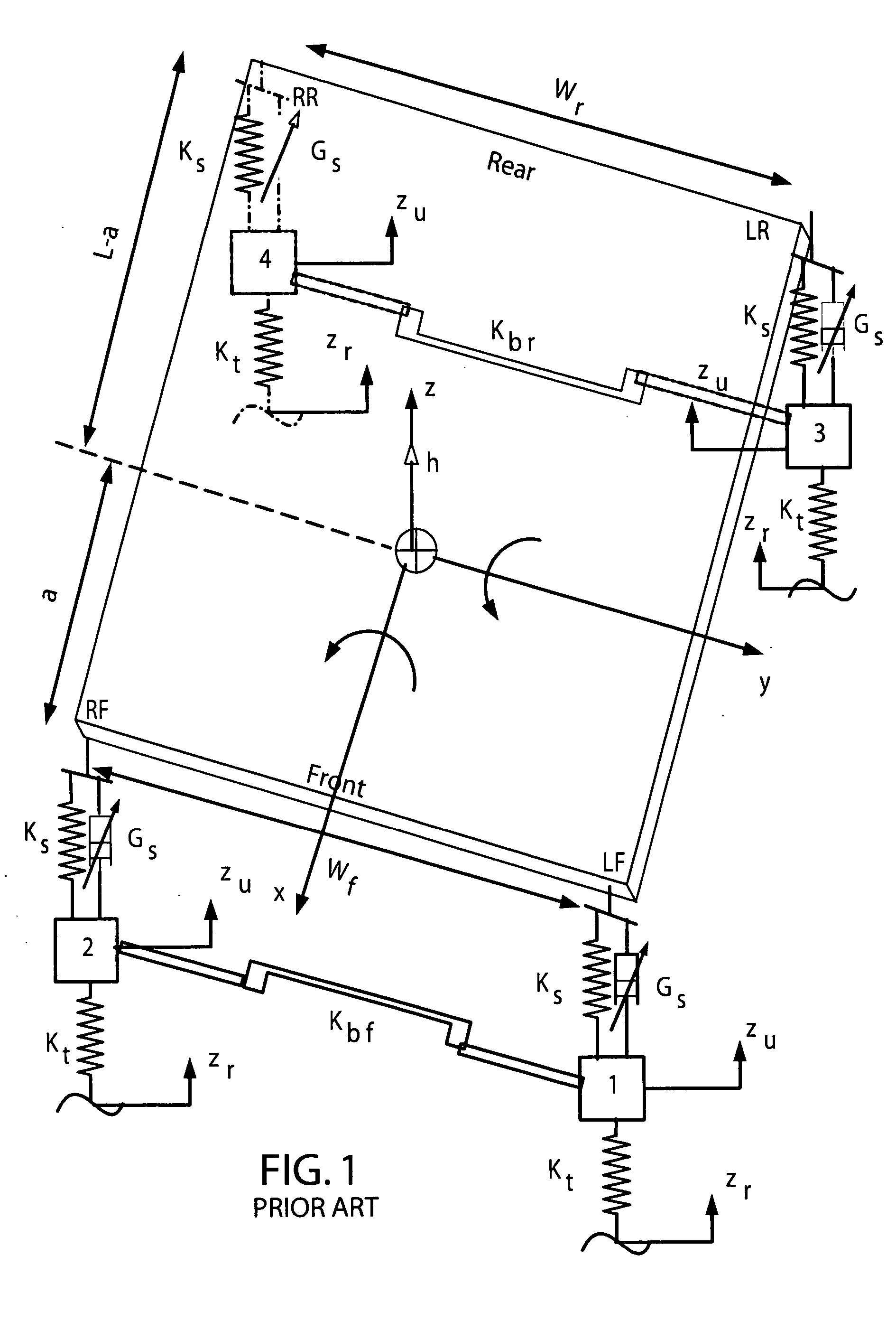
[0074] Referring to FIG. 1, the following parameters have been used for the vehicle model to demonstrate the simulation results presented in this section: sprung mass (ms)=1528 kg, front unsprung mass (muf)=111 kg, rear unsprung mass (mur)=141 kg, roll moment of inertia (Ixx)=515 kg.m2, pitch moment of inertia (Iyy)=2853 kg.m2, tire stiffness (Kt)=240.5 kN / m, front spring stiffness (Ksf)=30.6 kN / m, rear spring stiffness (Ksr)=26 kN / m, front roll bar stiffness (Kbf)=27.3 kN / m, rear roll bar stiffness (Kbr)=10 kN / m, wheelbase (L)=2.9 m, track width (wf,r)=1.5 m, c.g. distance behind front axle (a)=1.3 m, roll center height (hf,r): front=0.11 m; rear=0.13 m, c.g. height (hcg)=0.6 m; open-loop damping (Gop): front=300 N / mis: rear=150 N / m / s, passive damping (Gp): front=2.2 kN / m / s; rear=1.4 kN / m / s.

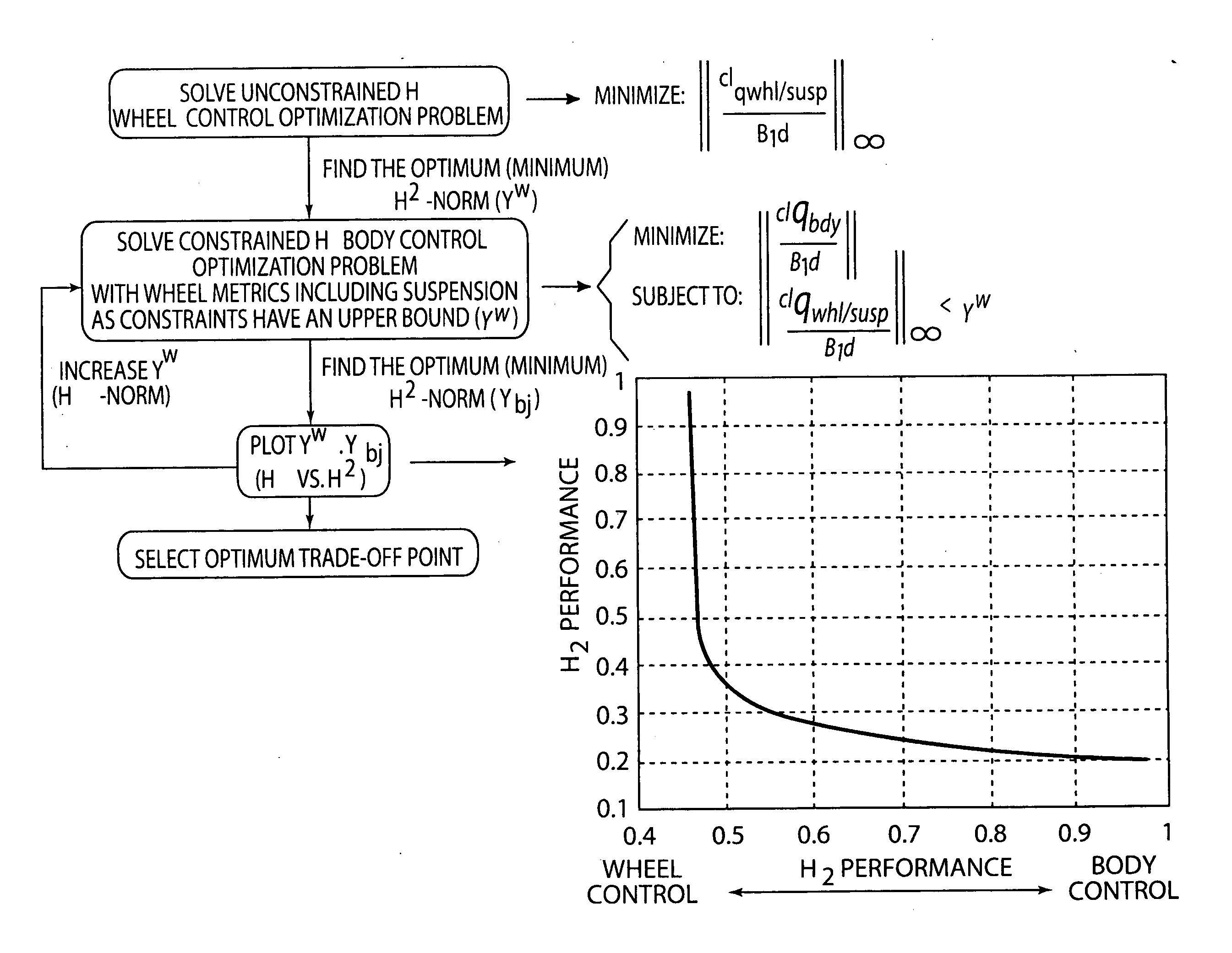
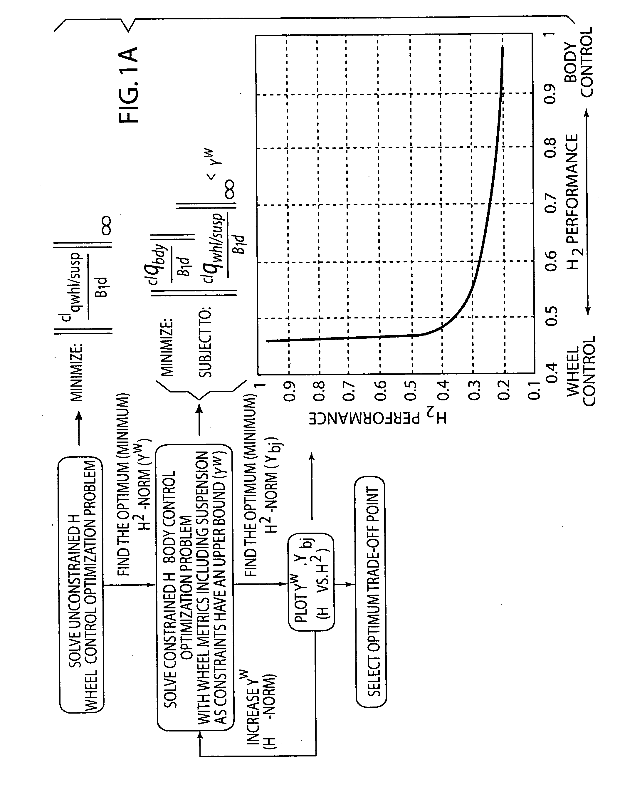
[0075] The synthesis procedure described above is utilized to solve an unconstrained wheel control problem by minimizing the H∞-norm of the metrics. The optimal solution (γω) for this example i...


PUM


Abstract

A procedure for synthesizing a state-feedback gain matrix for a vehicle suspension system including active suspension components such as continuously variable semi-active dampers is disclosed. Sensors and / or estimation schemes provide feedback to the controller concerning the vehicle states. A set of frequency-weighted metrics are first quantified and used as part of a full car 7 degree of freedom vehicle model to construct a constrained multi-objective optimization problem. Using commercially available software, a mixed H2 / H∞ problem is iteratively solved to minimize a set of body control objectives subject to a set of physical control and wheel control related constraints to obtain data, preferably in the form of a plot of the trade-off curve between optimum wheel control and optimum body control. An initial design point is selected from the trade-off curve to calculate a state-feedback gain matrix that provides a reasonable balance between body and wheel control objectives. Additional points may be selected from the trade-off curve to iteratively provide an optimal solution.

Description

TECHNICAL FIELD [0001] The present invention relates generally to a method of controlling a variable damping semi-active suspension arrangement for an automotive unit. More specifically, the invention is directed to a system and controller for a semi-active suspension damper assembly including position sensors be used by a control unit to determine the control gains that alter the damping characteristics of the suspension system based upon minimization of body control metrics subject to wheel control constraints to optimize the trade-off between ride comfort and vehicle handling. BACKGROUND OF THE INVENTION [0002] Fully active and semi-active vehicle suspension systems have been developed in an effort to improve both ride comfort and vehicle road-holding performance (“handling”). These suspension systems may include a controller that generates signals to the active suspension components based upon vehicle operating conditions that are measured by sensors. The controller includes a c...

Claims


Application Information

Patent Timeline
IPC IPC(8): B60G17/018
CPCB60G17/018B60G17/0182
Inventor GADE, PRASAD V.
Owner DELPHI TECH INC
Why Eureka
Try Eureka