Film pattern forming method, device, electro-optical apparatus, and electronic appliance

Inactive Publication Date: 2007-05-24
SEIKO EPSON CORP
View PDF1 Cites 0 Cited by
  • Summary
  • Abstract
  • Description
  • Claims
  • Application Information

AI Technical Summary

Benefits of technology

[0009] The advantage of the invention is to provide a film pattern forming method that stably forms a pattern while maintaining a prescribed function, as well as to provide a device, an electro-optical apparatus, and an electronic apparatus that are produced using the method.
[0010] In order to achieve the above-referenced advantage, each aspect of the present invention is provided as follows.
[0011] According to a first aspect of the invention, a method for forming a film pattern by disposing a functional fluid on a substrate, includes: forming a partition wall that includes a first opening that corresponds to a first film pattern and a second opening that corresponds to a second film pattern; and disposing a droplet of the functional fluid into the first opening, so that the functional fluid is disposed into the second opening by a self-flow of the functional fluid; wherein: the first film pattern is linear; the second film pattern is narrower than the first film pattern, and is connected to the first film pattern at a rear edge thereof; and a front edge of the second film pattern has a missing part in which a corner of a rectangular contour is missing.
[0012] Therefore, in the film pattern forming method according to the first aspect of the invention, the missing part of the front edge need not have a functional liquid flown in, while the functional fluid are deposited from the first opening into the second opening utilizing the self-flow of the functional fluid. Hence, the flow length is shortened, which allowing a stable film pattern formation. Moreover, the prescribed function is maintained, since, according to this aspect of the invention, the missing part is in the front edge of the second film pattern.
[0013] It is desirable that the missing part be shaped in the shape based on the rheological characteristics of the functional fluid. Therefore, according to this aspect of the invention, the time during which the functional fluid is deposited into the second opening in the second film pattern is shortened, by shaping the missing part in accordance with the flow-speed distribution of the functional fluid; thereby improving the productivity.
[0014] Moreover, it is desirable that the missing part be formed outside of a functional region in the second film pattern.

Problems solved by technology

Moreover, there are problems such as: those equipments requiring complex processes in order to form wirings and other elements that are constituted of predetermined patterns; and the manufacturing cost being high, since the material usage efficiency is approximately several percents, most of the materials unavoidably being disposed.
However, in a pattern forming method using the droplet discharge method described above, the discharged droplets spread out on a substrate after the landing, making it difficult to stably form the minute patterns.
Especially when the pattern is a conductive film, the spread droplets cause liquid retention pits (bulges), possibly resulting to be a cause of defects such as disconnection and short circuit.
The common technique described above, however, involves the following problem.

Method used


Image

  • Film pattern forming method, device, electro-optical apparatus, and electronic appliance
  • Film pattern forming method, device, electro-optical apparatus, and electronic appliance
  • Film pattern forming method, device, electro-optical apparatus, and electronic appliance

Examples


Embodiment Construction

[0045] Embodiments of a film pattern forming method, a device, an electro-optical device, and an electronic apparatus will now be described with references to the accompanying drawings.

[0046] The embodiments described hereafter merely represent some of the embodiments for the present invention, and shall not limit the invention. Figures used in the description hereafter have different scale sizes modified for each of the layers and components, so that each of them will have a size large enough to be recognized in the figures.

[0047] Droplet Discharge Device

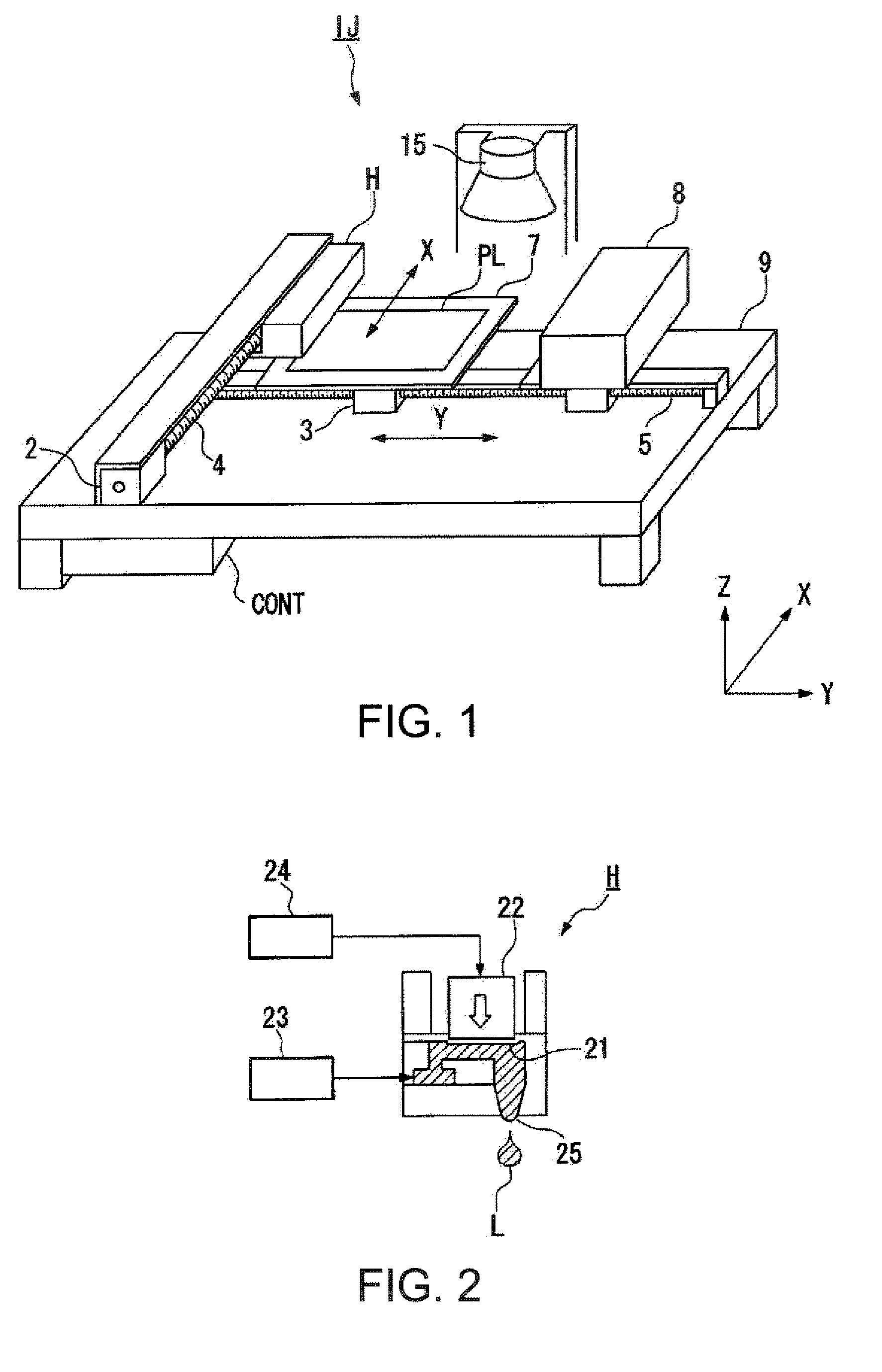
[0048] First, according to one embodiment of the invention, a droplet discharge device used for forming film patterns is described with reference to FIG. 1.

[0049]FIG. 1 is an oblique drawing showing a schematic configuration of a droplet discharge device (an inkjet device) IJ that deposits a liquid material to a substrate with the droplet discharge method, the device being indicated as an example of a device used in the film pa...


PUM


Abstract

A method for forming a film pattern by disposing a functional fluid on a substrate, includes: forming a partition wall that includes a first opening that corresponds to a first film pattern and a second opening that corresponds to a second film pattern; and disposing a droplet of the functional fluid into the first opening, so that the functional fluid is disposed into the second opening by a self-flow of the functional fluid; wherein: the first film pattern is linear; the second film pattern is narrower than the first film pattern, and is connected to the first film pattern at a rear edge thereof; and a front edge of the second film pattern has a missing part in which a corner of a rectangular contour is missing.

Description

BACKGROUND [0001] 1. Technical Field [0002] The present invention relates to a film pattern forming method, a device, electro-optical apparatus, and an electronic apparatus. [0003] 2. Related Art [0004] A method such as photolithography is widely utilized as a method for forming a predetermined patterned wiring and other elements that are used for an electronic circuit, an integrated circuit or the like. The photolithography requires large-scale equipments such as a vacuum apparatus and an aligner. Moreover, there are problems such as: those equipments requiring complex processes in order to form wirings and other elements that are constituted of predetermined patterns; and the manufacturing cost being high, since the material usage efficiency is approximately several percents, most of the materials unavoidably being disposed. [0005] Compared with the above, a droplet discharge method, or, a so-called inkjet method has been suggested for forming the wirings and other elements that a...

Claims


Application Information

Patent Timeline
IPC IPC(8): H01L21/00
CPCG02F2001/136295H05K3/125H05K3/1258H05K2201/09272H05K2201/09727H05K2203/013H05K2203/0568G02F1/136295H01L21/288
Inventor HIRAI, TOSHIMITSUMORIYA, KATSUYUKI
Owner SEIKO EPSON CORP
Why Eureka
Try Eureka