
Power tool with improved start actuator

Active Publication Date: 2007-05-24
STANLEY WORKS THE
View PDF27 Cites 21 Cited by
  • Summary
  • Abstract
  • Description
  • Claims
  • Application Information

AI Technical Summary

Benefits of technology

[0011] Accordingly, one aspect of one or more embodiments of the present invention provides means to discourage the tool operator's hand from coming in contact with a potential hazard such as a pinch point or the intermittently exposed gear teeth of a rotating gear driven socket during the normal operation of the power tool.
[0012] Another aspect of one or more embodiments of the present invention provides a dual-start-actuator system that allows the tool operator to use a hand-held power tool in an efficient manner and that minimally interferes with the ability to manipulate the tool in order to perform its intended operation.
[0013] Another aspect of one or more embodiments of the present invention provides a dual-start-actuator system that discourages the operator from intentionally defeating the intended purpose of the dual start actuators by mechanically fixing either actuator into its ON position.
[0014] Another aspect of one or more embodiments of the present invention provides a primary or secondary start actuator that is more convenient to actuate in a variety of power tool orientations.
[0015] Another aspect of one or more embodiments of the present invention provides a power tool with an improved dual start actuator system that is simple and inexpensive to manufacture, but is nonetheless robust enough to be conveniently implemented onto a variety of power tools.

Problems solved by technology

Certain power tools can be so configured that there exists an operator hazard should the operator inadvertently place his hands near a potential pinch point.
Several types of tool configurations present such hazards which, if guarded, would prevent the tool from being used for its intended purpose.
Unfortunately, positioning a guard in the vicinity of the output drive might interfere with the tool's ability to reach the fastener to be tightened.
Such multi-step start actuators reduce the likelihood of unintentionally starting the tool, but do not prevent an operator's free second hand from coming in contact with a pinch point or hazard.
However, the restrictive positioning and inconvenient actuation of the secondary actuator typically hinders the normal operation of the tool as it is manipulated into position onto fasteners in a variety of positions.
In such cases an operator may choose to defeat the intended safety function of the secondary start actuator by mechanically restraining it in its ON position.
In addition, when a secondary start actuator is positioned at a preferred location on the body of the tool, the physical size of typical commercially available electrical switches adds considerable size and weight to the hand-held assembly tool, placing an ergonomic burden on the operator.
It is also often difficult and costly to route the electrical wires to the electrical switch associated with this secondary start actuator in a manner that prevents their damage when used in an industrial environment, thereby adding considerable cost and complicating any future maintenance of the tool.

Method used


Image

  • Power tool with improved start actuator
  • Power tool with improved start actuator
  • Power tool with improved start actuator

Examples


Embodiment Construction

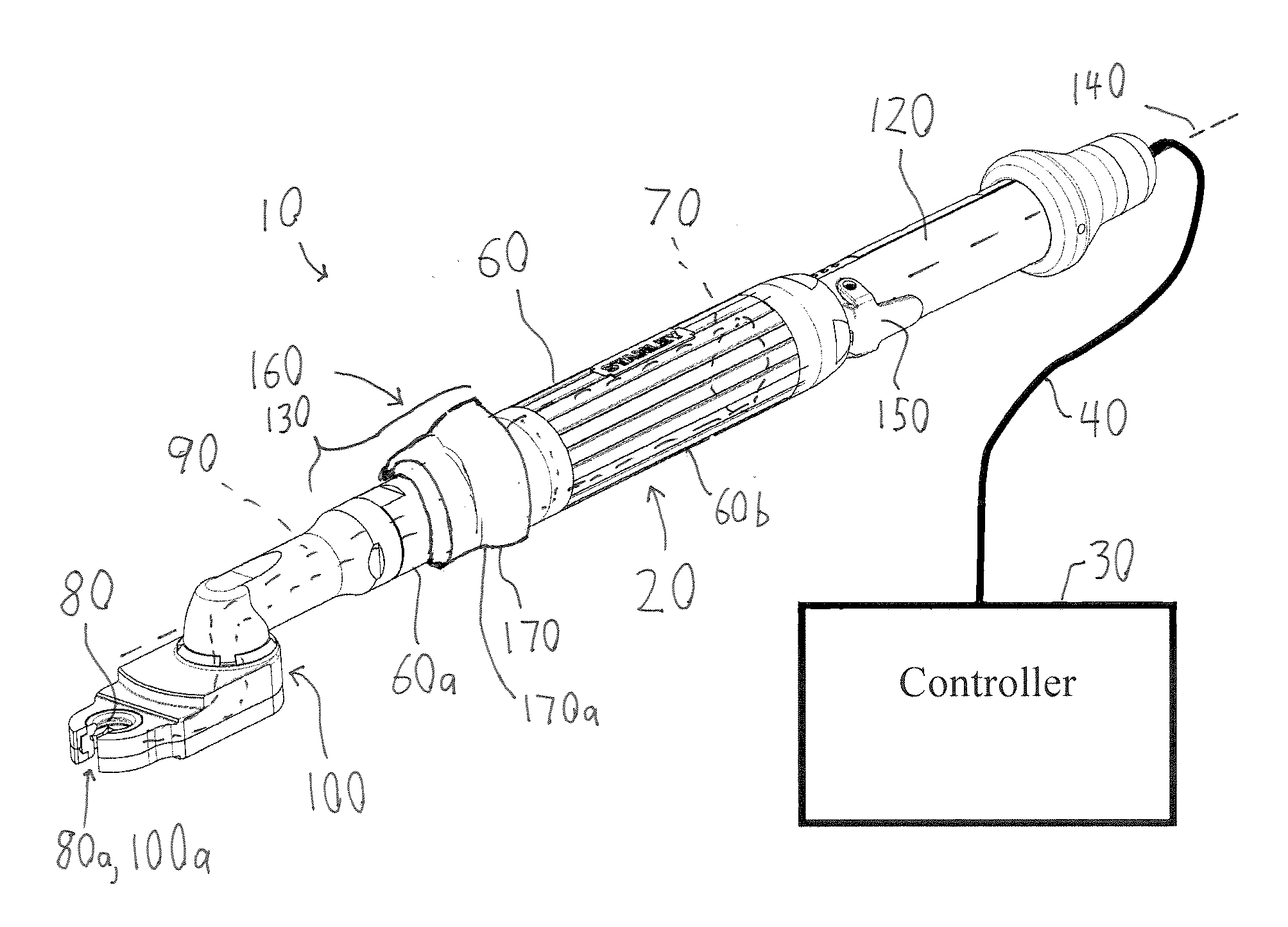
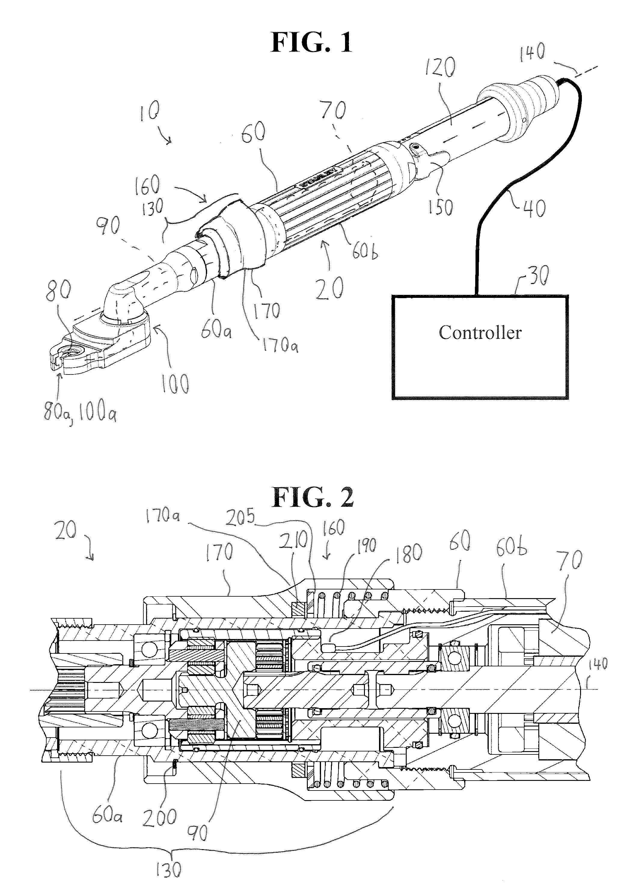
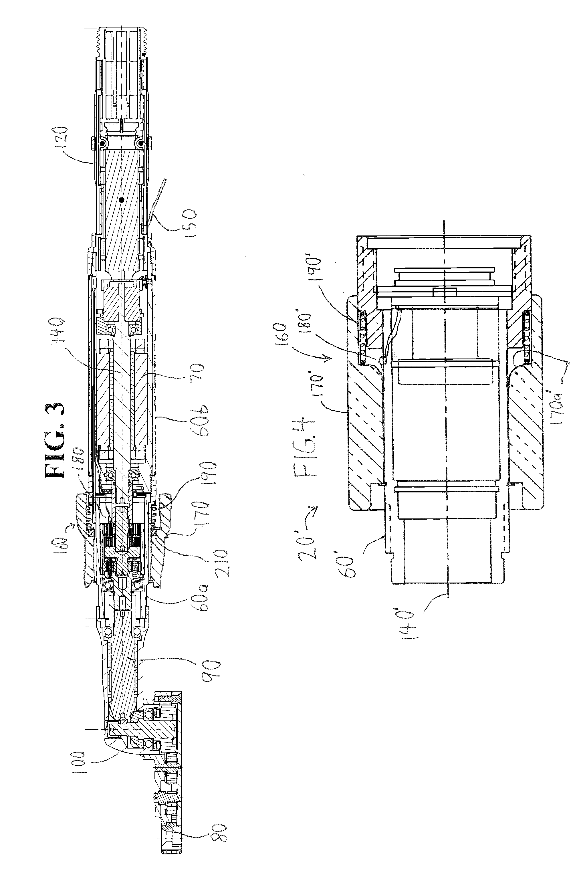
[0029]FIG. 1 illustrates a power tool system 10 according to an embodiment of the present invention. The system 10 comprises a powered assembly tool 20, a controller 30, and a cable 40 operatively interconnecting the tool 20 and controller 30. In the illustrated embodiment, the controller 30 and tool 20 are separately housed. However, according to an alternative embodiment, the controller 30 is integrated into a housing 60 of the tool 20. Alternatively, some aspects of the controller 30 may be housed within the housing 60 while other aspects of the controller 30 may remain separately housed.

[0030] The illustrated tool 20 comprises an open-end nutrunner. However, the tool 20 may alternatively comprise any other type of hand-held, torque-applying, powered assembly tool (e.g., straight, angle, crowfoot, and / or pistol-grip power wrenches) or other hand-held power tool (e.g., drill, jigsaw, circular saw, router, etc.) without deviating from the scope of the present invention. Hand-held ...


PUM

PropertyMeasurementUnit
Currentaaaaaaaaaa
Timeaaaaaaaaaa
Torqueaaaaaaaaaa

Abstract

A power tool system includes a two-handed power tool having first and second start actuators, one for each hand of an operator. A controller prevents the power tool from initiating an operating cycle unless both actuators are turned ON to reduce the possibility of the operator's hands being disposed in a hazardous position during operation of the power tool. To discourage manual override of the dual-start-switch system, the controller prevents the power tool from initiating an additional operating cycle until both actuators have been switched OFF and then ON again. The second actuator includes a tubular sleeve that extends over part of the power tool to allow the sleeve to slide axially relative to the power tool between ON and OFF positions. Axial movement of the sleeve from its OFF position to its ON position turns ON the second start actuator.

Description

CROSS REFERENCE [0001] This application claims the benefit of priority from U.S. Provisional Application Ser. No. 60 / 785,380, filed Mar. 24, 2006, titled “Power Tool with Improved Start Actuator,” the entire contents of which are hereby incorporated by reference.BACKGROUND OF THE INVENTION [0002] 1. Field of the Invention [0003] This invention relates to start actuators for power tools such as power wrenches. [0004] 2. Description of Related Art [0005] Hand-held powered assembly tools (e.g., straight, angle, crowfoot, open end, and / or pistol-grip power wrenches), typically include a motor (e.g., an electric or fluid-driven motor), an output drive connected to the motor via a drive train, and a manually operated start switch to initiate operation of the tool. The output drive (e.g., a socket or a square drive spindle adapted to engage a socket) is shaped to engage a further output drive (e.g., a socket) or a fastener to be tightened or loosened (e.g., nuts, bolts, screws, etc.). [000...

Claims


Application Information

Patent Timeline
IPC IPC(8): B23Q5/00B23B45/00B27C3/08
CPCB25B21/00B25F5/00F16P3/20
Inventor STEVERDING, JAMES F.PANKEY, GLEN A.BOOKSHAR, DUANE R.
Owner STANLEY WORKS THE
Learn More