High flow, low vacuum carbon canister purge valve

a carbon canister and purge valve technology, applied in the direction of condensed fuel collection/return, charge feed system, non-fuel substance addition to fuel, etc., can solve the problems of insufficient purge flow, inability to purge the canister, and inability to clean the canister. the effect of low pressur

Inactive Publication Date: 2007-05-24
SIEMENS VDO AUTOMOTIVE CORP
View PDF9 Cites 9 Cited by
  • Summary
  • Abstract
  • Description
  • Claims
  • Application Information

AI Technical Summary

Benefits of technology

[0014] One embodiment of the present invention is a high flow purge valve apparatus for a fuel tank ventilation system. The ventilation system has an adsorption canister venting a fuel tank, and a canister purge valve connecting the canister to an intake manifold of an internal combustion engine. The high flow purge valve apparatus includes a nozzle connected between the canister purge valve and the adsorption canister, the nozzle having a pressure tap such that a purge flow from the adsorption canister to the canister purge valve creates low pressure i

Problems solved by technology

Hydrocarbon pollutants accumulate in the charcoal canister during periods when the engine is off and the vehicle is not in use.
During those periods, it is not possible to purge the canister because no manifold vacuum is available.
Certain engine designs have inherently low intake manifold vacuum.
In each of those cases, the low manifold vacuum, combined with the small flow path diameters typical of a canister purge valve as de

Method used


Image

  • High flow, low vacuum carbon canister purge valve
  • High flow, low vacuum carbon canister purge valve
  • High flow, low vacuum carbon canister purge valve

Examples


Embodiment Construction

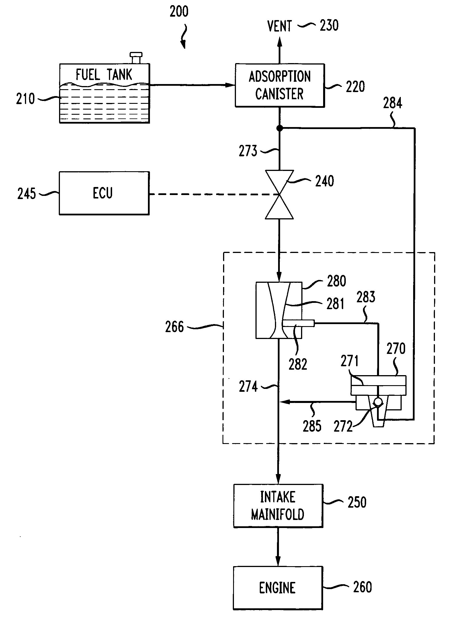
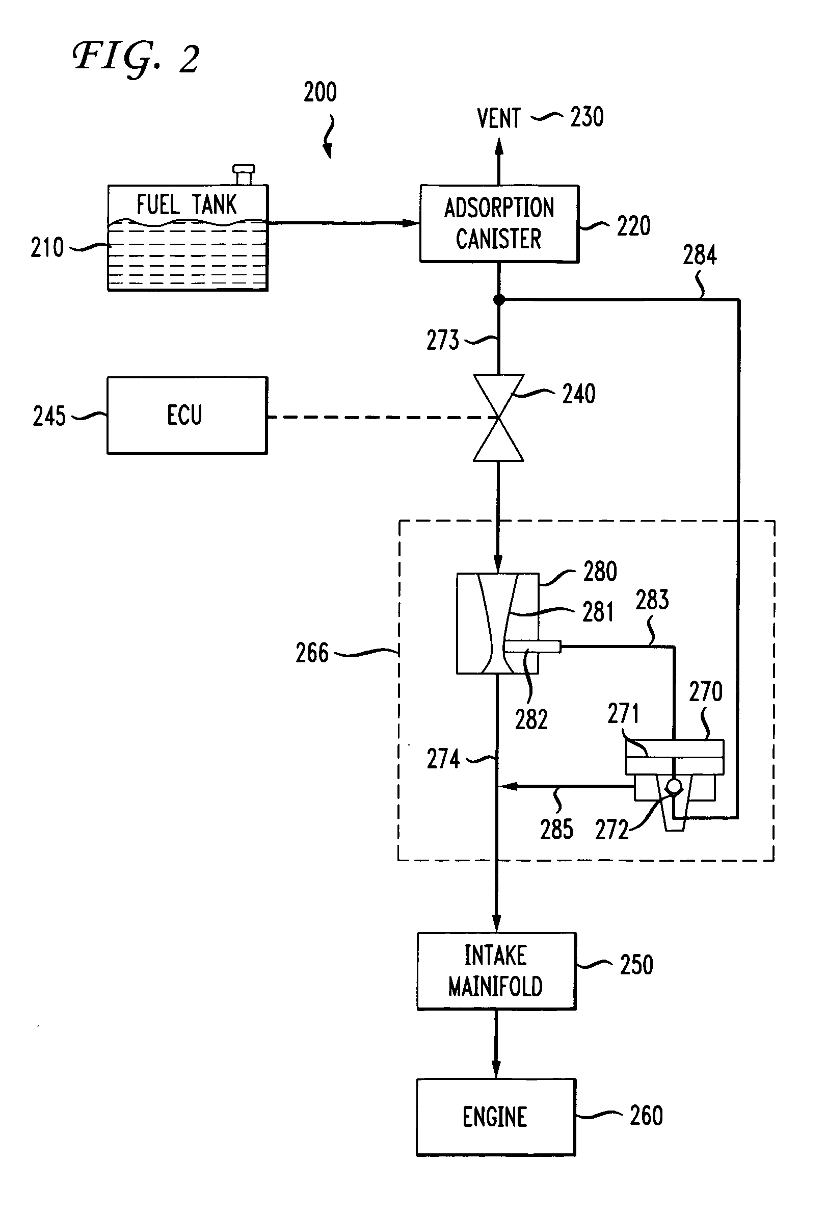
[0030] A fuel tank ventilation system 200 in accordance with one embodiment of the invention is shown schematically in FIG. 2. Elements corresponding to elements shown inFIG. 1 are indicated in FIG. 2 with element numbers indexed by 100. The fuel tank 210 is vented through an adsorption canister 220 to atmosphere through the vent 230. As in the arrangement described with reference to FIG. 1, during a purge cycle, a canister purge valve 240 is activated and controlled by an ECU 245, allowing the intake manifold 250 to draw outside air through the vent 230 and through the canister 220, purging accumulated hydrocarbons from the adsorption media in the canister. The purged hydrocarbons are combusted in the engine 260.

[0031] The present invention comprises a high flow, low vacuum purging system 266 that supplements the flow through the canister purge valve 240. A nozzle 280 is placed in the purge flow path 273, 274 between the canister purge valve 240 and the intake manifold 250. The no...


PUM


Abstract

A technique is provided for purging an adsorption canister in a fuel tank vent system. The technique provides a relatively high purge flow under conditions wherein the intake manifold vacuum is relatively low. A sonic nozzle is placed in the purge line between the existing purge valve and the adsorption canister. The sonic nozzle includes a tap at its throat for producing a vacuum in response to flow in the purge line. The vacuum is used to control a vacuum operated diaphragm valve in a parallel purge line. The system therefore supplements purge flow through the adsorption canister to the intake manifold.

Description

CROSS REFERENCE TO RELATED APPLICATIONS [0001] This application claims the benefit of U.S. Provisional Patent Application Ser. No. 60 / 732,031 entitled “High Flow, Low Vacuum Carbon Canister Purge Valve,” filed on Nov. 1, 2005, the contents of which are hereby incorporated by reference herein in their entirety.FIELD OF THE INVENTION [0002] The present invention relates generally to the field of fuel system emissions control, and more particularly, to techniques and systems for purging an adsorption canister used to remove hydrocarbon pollutants from the vent effluent of a fuel tank. BACKGROUND OF THE INVENTION [0003] Conventional fuel systems for vehicles with internal combustion engines may include a canister that accumulates fuel vapor from the headspace of the fuel tank. The canister typically contains an adsorption medium such as activated charcoal that adsorbs hydrocarbon pollutants in the vented fuel vapor before the vent effluent is released into the atmosphere. [0004] Activat...

Claims


Application Information

Patent Timeline
IPC IPC(8): F02M25/08
CPCF02M25/0836
Inventor BALSDON, DAVID WILLIAM
Owner SIEMENS VDO AUTOMOTIVE CORP
Why Eureka
Try Eureka