
Processor utilizing a loop buffer to reduce power consumption

a loop buffer and microprocessor technology, applied in the field of microprocessors, can solve the problems of large power consumption of microprocessors, undesirable and/or impractical many-purpose applications of conventional fetch units, etc., and achieve the effect of reducing power consumption

Inactive Publication Date: 2007-05-17
ARM FINANCE OVERSEAS LTD
View PDF36 Cites 54 Cited by
  • Summary
  • Abstract
  • Description
  • Claims
  • Application Information

AI Technical Summary

Benefits of technology

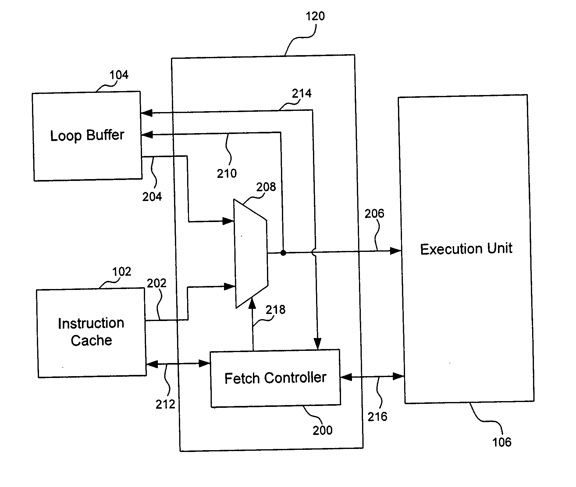
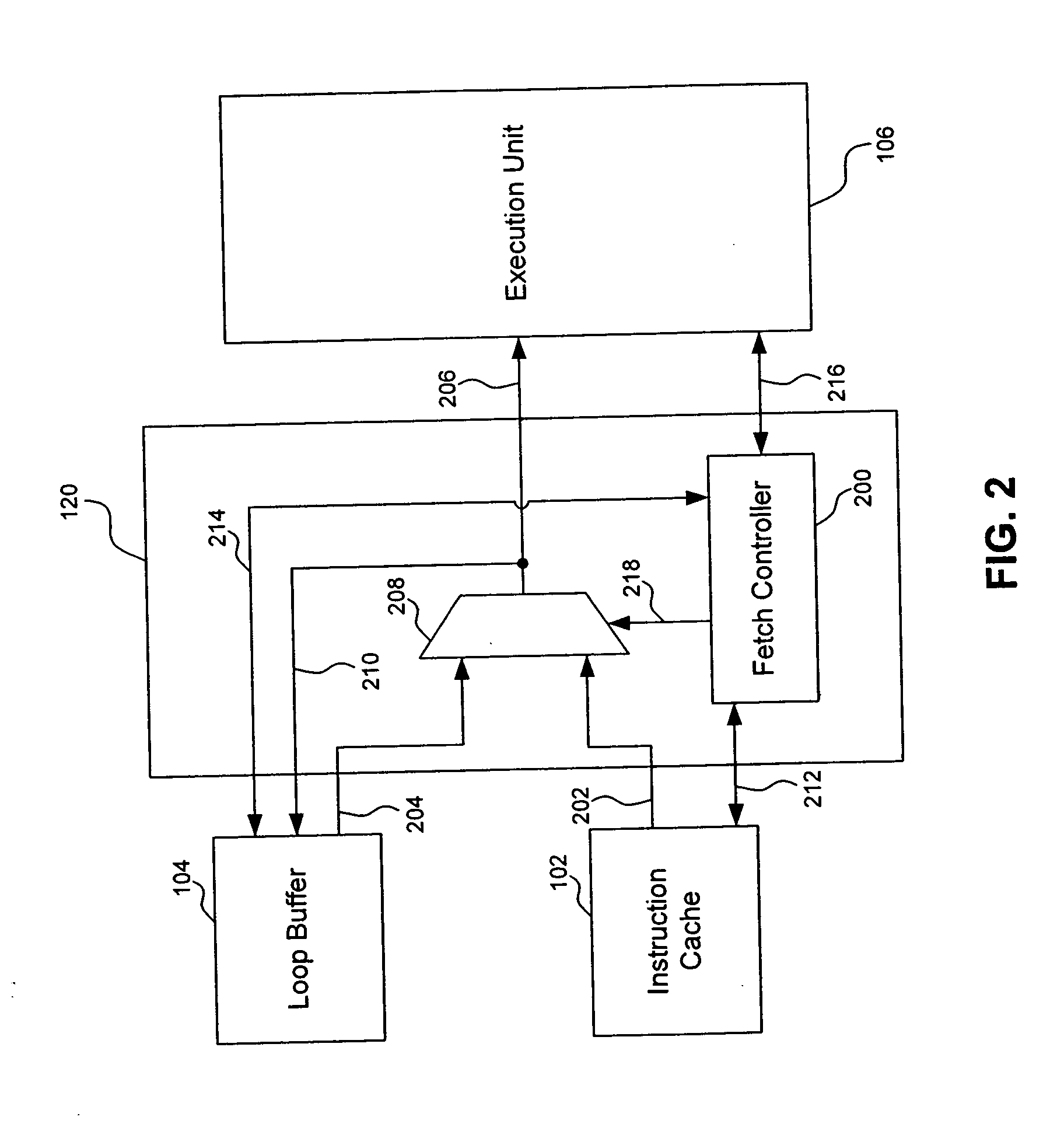
[0005] The present invention provides processing systems, apparatuses, and methods for utilizing a loop buffer to reduce power consumption.
[0007] In one embodiment, the loop buffer is disabled when not providing instructions to the execution unit to further reduce the total power consumed by the processor.
[0009] In one embodiment, when a component is disabled to reduce power consumption, a bias voltage is applied to the component to further reduce power consumption resulting from leakage.

Problems solved by technology

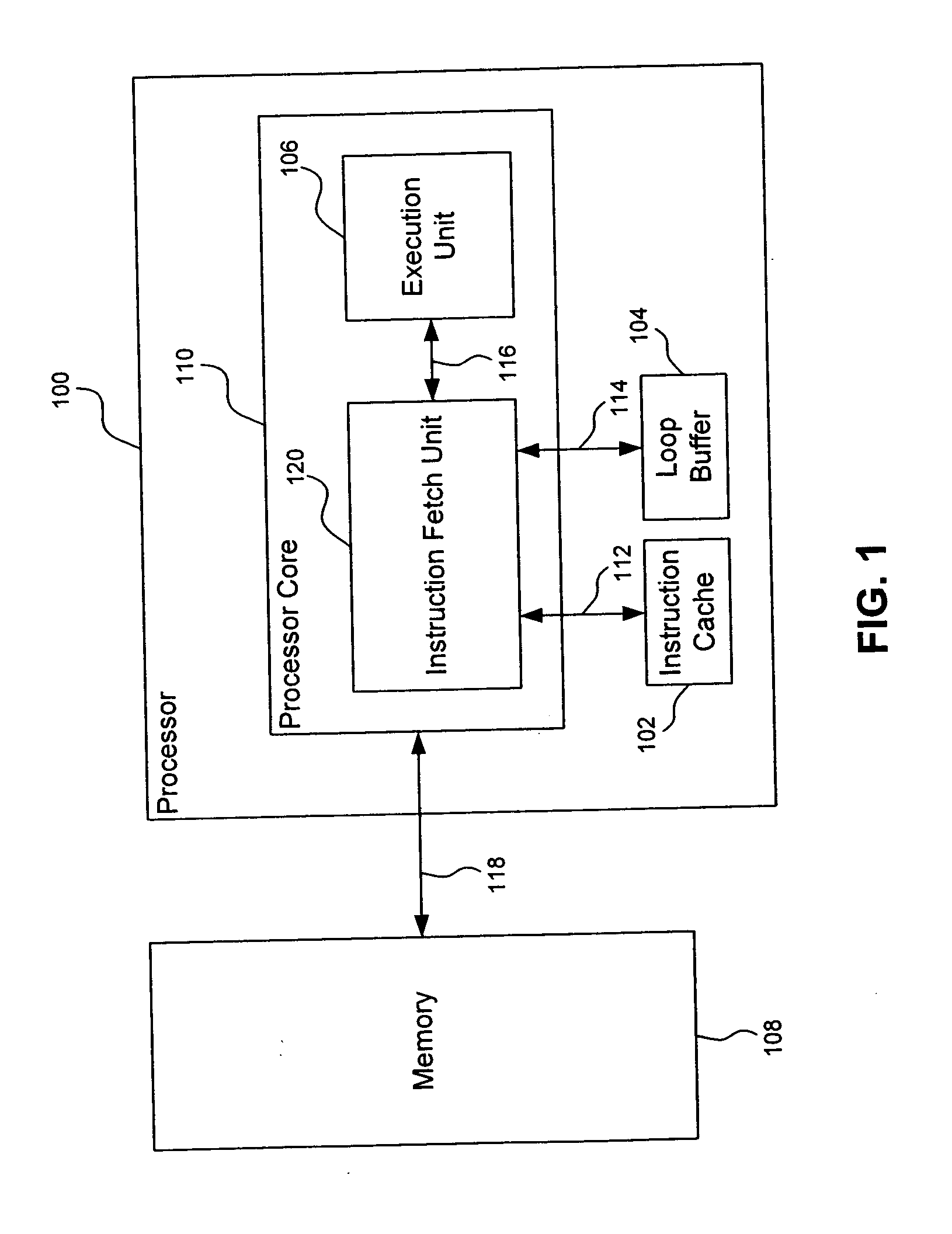
While conventional fetch units work for their intended purpose, they consume a significant amount of the total power of a microprocessor.
This makes microprocessors having conventional fetch units undesirable and / or impractical for many applications.

Method used


Image

  • Processor utilizing a loop buffer to reduce power consumption
  • Processor utilizing a loop buffer to reduce power consumption
  • Processor utilizing a loop buffer to reduce power consumption

Examples


first embodiment

[0029] In a first embodiment, step 304 is performed by configuring the loop buffer to store each instruction that is provided by the instruction cache to the execution unit. When a branch instruction provided to the execution unit is taken or predicted to be taken and the branch taken instruction is present in the loop buffer, a loop is determined to be stored in the loop buffer. Furthermore, when a jump instruction is provided to the execution unit and the jump target instruction is present in the loop buffer, a loop is determined to be stored in the loop buffer. For ISAs that require delay slot instructions, the delay slot instructions are provided to the execution unit and stored in loop buffer before a check is made to determine if the branch taken instruction or the jump target instruction is present in the loop buffer.

[0030] In the first embodiment, the loop buffer is flushed when a branch target instruction or a jump target instruction is not present in the loop buffer and th...

second embodiment

[0032] In a second embodiment, step 304 is performed by configuring the loop buffer to only store instructions when instructions potentially forming a loop are provided from the instruction cache to the execution unit. Initially, the loop buffer is disabled from storing instructions. When a branch instruction provided from the instruction cache to the execution unit is taken or predicted to be taken, and the branch taken instruction occurs earlier in the instruction sequence, the branch instruction is presumed to form a loop. Furthermore, when a jump instruction is provided from the instruction cache to the execution unit, and the jump target instruction occurs earlier in the instruction sequence, the jump instruction is presumed to form a loop. Once a potential loop is identified, the size of the loop is calculated (delay slot instructions are accounted for ISAs which require them) and if the potential loop is capable of fitting in the loop buffer, a loop that can be stored in the ...


PUM


Abstract

The present invention provides processing systems, apparatuses, and methods that reduce power consumption with the use of a loop buffer. In an embodiment, an instruction fetch unit of a processor initially provides instructions from an instruction cache to an execution unit of the processor. While instructions are provided from the instruction cache to the execution unit, instructions forming a loop are stored in a loop buffer. When a loop stored in the loop buffer is being iterated, the instruction cache is disabled to reduce power consumption and instructions are provided to the execution unit from the loop buffer. When the loop is exited, the instruction cache is re-enabled and instructions are provided to the execution unit from the instruction cache.

Description

CROSS REFERENCE TO RELATED APPLICATIONS [0001] This application is related to commonly owned, co-pending U.S. application Ser. No. ______ (Attorney Docket No. 1778.2070000), filed on the same date herewith, entitled “Processor Utilizing A Scratch Pad On-Demand To Reduce Power Consumption,” and commonly owned, co-pending U.S. application Ser. No. ______ (Attorney Docket Number 1778.2080000), filed on the same date herewith, entitled “Microprocessor Having A Power-Saving Instruction Cache Way Predictor And Instruction Replacement Scheme,” each of which is incorporated herein by reference in its entirety. FIELD OF THE INVENTION [0002] The present invention relates generally to microprocessors and reducing power consumption in microprocessors. BACKGROUND OF THE INVENTION [0003] An instruction fetch unit of a microprocessor is responsible for continually providing the next appropriate instruction to the execution unit of the microprocessor. A conventional instruction fetch unit typically...

Claims


Application Information

Patent Timeline
IPC IPC(8): G06F9/44
CPCG06F1/3203G06F1/3275G06F1/3287Y02B60/1228G06F9/381Y02B60/1282G06F9/325Y02D10/00
Inventor KNOTH, MATTHIAS
Owner ARM FINANCE OVERSEAS LTD
Learn More