
Water reclamation in a micropower generator

Active Publication Date: 2007-05-10
HONEYWELL INT INC
View PDF14 Cites 71 Cited by
  • Summary
  • Abstract
  • Description
  • Claims
  • Application Information

AI Technical Summary

Benefits of technology

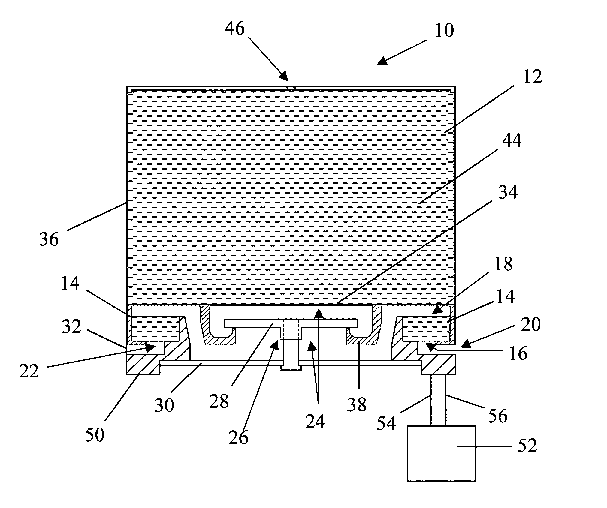
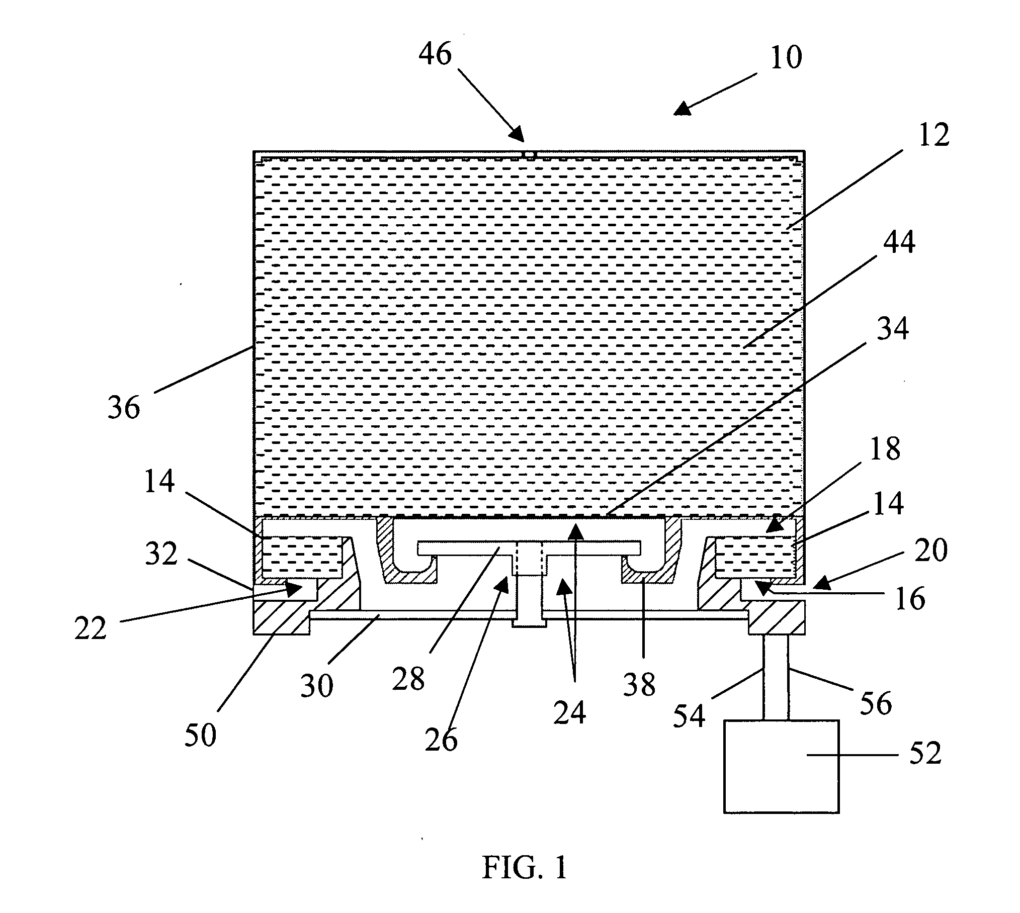
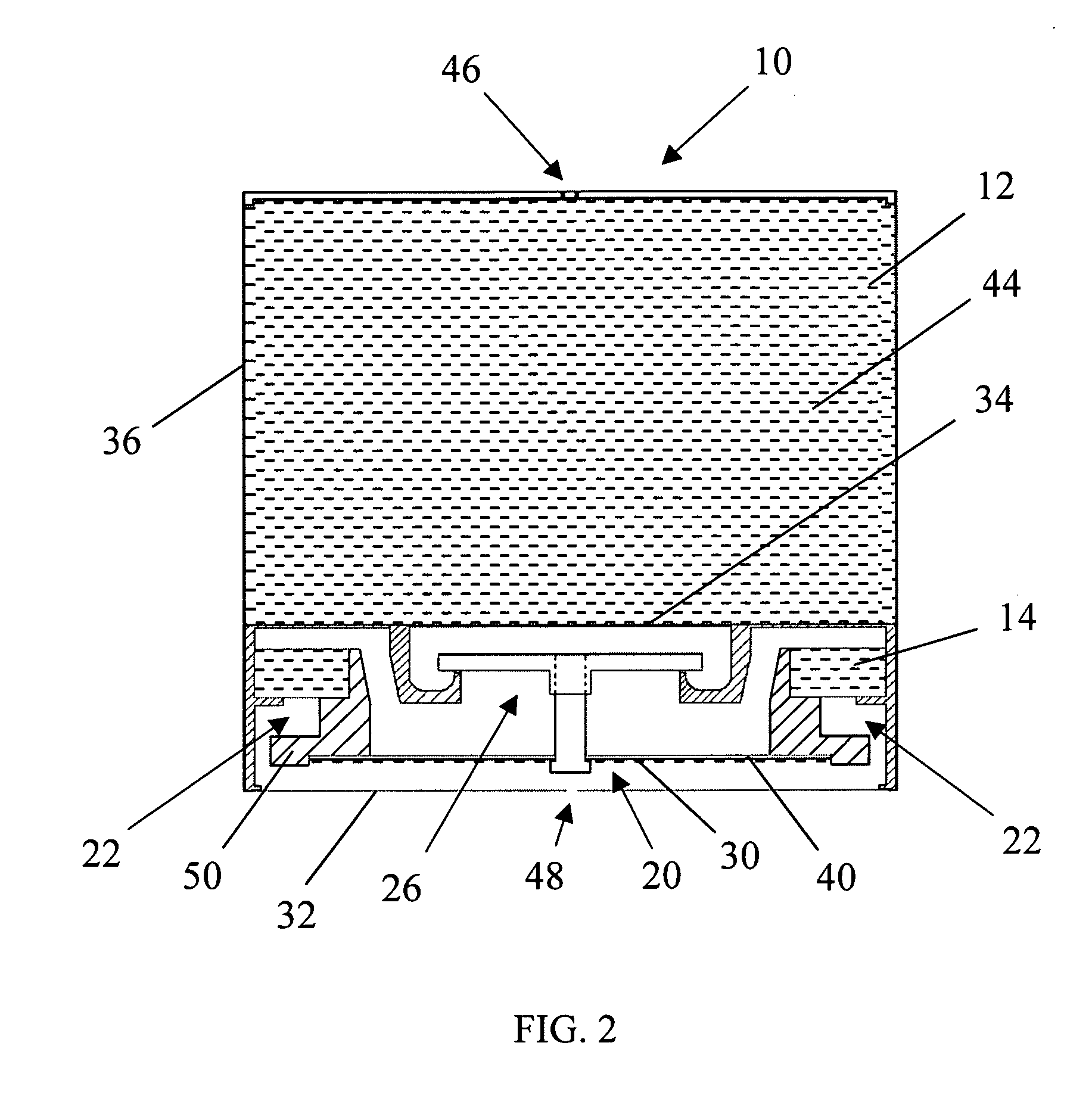
[0014] e) a water retention zone within the housing extending from the air inlet to the fuel cell cathode, which water retention zone deters the diffusion of generated fuel cell water out of the air inlet; and
[0021] e) a water retention zone within the housing extending from the air inlet to the fuel cell cathode, which water retention zone deters the diffusion of generated fuel cell water out of the air inlet;
[0024] h) an oxygen permeable, water vapor impermeable membrane united with the air inlet, which membrane deters the flow of fuel cell water into the atmosphere; and
[0032] e) a water retention zone within the housing extending from the air inlet to the fuel cell cathode, which water retention zone deters the diffusion of generated fuel cell water out of the air inlet; and

Problems solved by technology

However, this system is undesirable in the long term because it is dependent upon a non-renewable resource.
While this method is useful, it is not preferred because the metal hydrides are typically very heavy, expensive and only release small quantities of hydrogen.
The disadvantages associated with this method is that reaction products from the chemical and liquid water typically form a cake or pasty substance which interferes with further reaction of the reactive chemical with the liquid water or acid.
This method is also disadvantageous in that the storage of liquid water fuel consumes additional space and increases the overall weight of the associated power generator.
Presently, the power source that is most often used for portable applications is the lithium battery, which has a limited energy capacity as a function of volume and especially as a function of weight.

Method used


Image

  • Water reclamation in a micropower generator
  • Water reclamation in a micropower generator
  • Water reclamation in a micropower generator

Examples


example 1

[0079] A power generator as seen in FIG. 1 was provided and given an initial flush of hydrogen gas. The initial flush evacuated air from the generator cavity, and was thereafter consumed by the fuel cell, producing electricity and byproduct water. Following consumption of this initial hydrogen flush, hydrogen gas was continuously generated internally, as well as electricity. The power output of the generator was measured over time. The results are shown in FIG. 5, which is a plot of the power output of the power generator versus time. Power output was initially set at 50 microWatts, but was later increased to 170 and then to 210 microWatts, where it was maintained for the duration of a 30 day test. During the first 20 days of the test, ambient laboratory air relative humidity varied between about 10 to 20 percent. Laboratory air temperature was about 23° C. The initial flush of hydrogen was estimated to have been consumed in about the first day of operation. For this waterless opera...


PUM


Abstract

A waterless power generator, particularly a waterless electrical power generator and a passively controlled process for producing electricity with a fuel cell using stoichiometric amounts of a solid hydrogen fuel and byproduct water vapor produced by the fuel cell to generate hydrogen gas. A fuel cell reaction of hydrogen and oxygen produces electrical energy as well as by-product water which diffuses back into the power generator as water vapor to react with the hydrogen fuel, producing more hydrogen gas. This generated hydrogen gas is then used as a fuel which allows the fuel cell to generate additional electrical power and additional water. The process runs without any attached water source or water supply other than the water which is produced by the fuel cells themselves.

Description

BACKGROUND OF THE INVENTION [0001] 1. Field of the Invention [0002] The invention relates to a waterless power generator. More particularly, the invention pertains to an electrical power generator and process for producing electrical power with a fuel cell. The reaction of oxygen and hydrogen gases in a fuel cell produces electricity and by-product water, which by-product water is reclaimed and used to produce additional hydrogen gas through its reaction with a solid hydrogen producing fuel. [0003] 2. Description of the Related Art [0004] Similar to batteries, fuel cells function to produce electricity through chemical reactions. Rather than storing reactants as batteries do, fuel cells are operated by continuously supplying reactants to the cell. In a typical fuel cell, hydrogen gas acts as one reactant and oxygen as the other, with the two reacting at electrodes to form water molecules and releasing energy in the form of direct current electricity. This direct current electricity ...

Claims


Application Information

Patent Timeline
IPC IPC(8): H01M8/04H01M8/06
CPCC01B3/065C01B2203/066H01M8/04089H01M8/04201H01M8/04208H01M8/04216H01M8/04291H01M8/065H01M8/2475H01M2008/1095Y02E60/362Y02E60/50Y02E60/36
Inventor EICKHOFF, STEVEN J.WOOD, ROLAND A.
Owner HONEYWELL INT INC
Learn More