Optical information recording and reproducing apparatus capable of coma aberration correction
a technology of optical information and recording apparatus, applied in the field of optical information recording and reproducing apparatus, can solve the problems of reducing imaging performance, preventing and reducing the size of the apparatus, so as to achieve stable recording and/or reproducing
- Summary
- Abstract
- Description
- Claims
- Application Information
AI Technical Summary
Benefits of technology
Problems solved by technology
Method used
Image
Examples
first embodiment
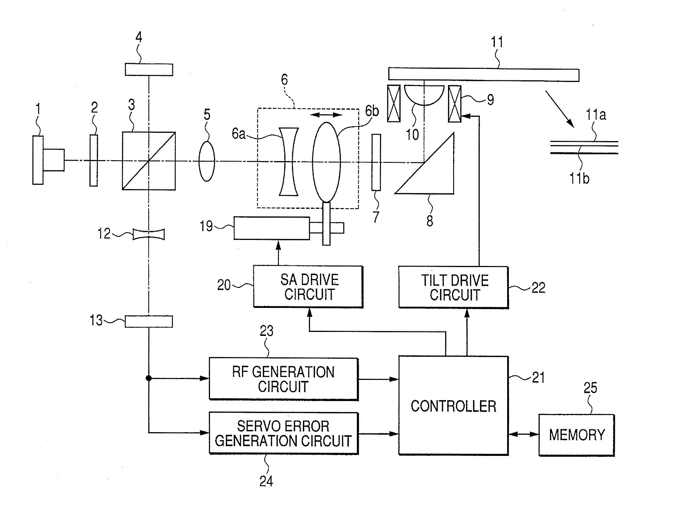
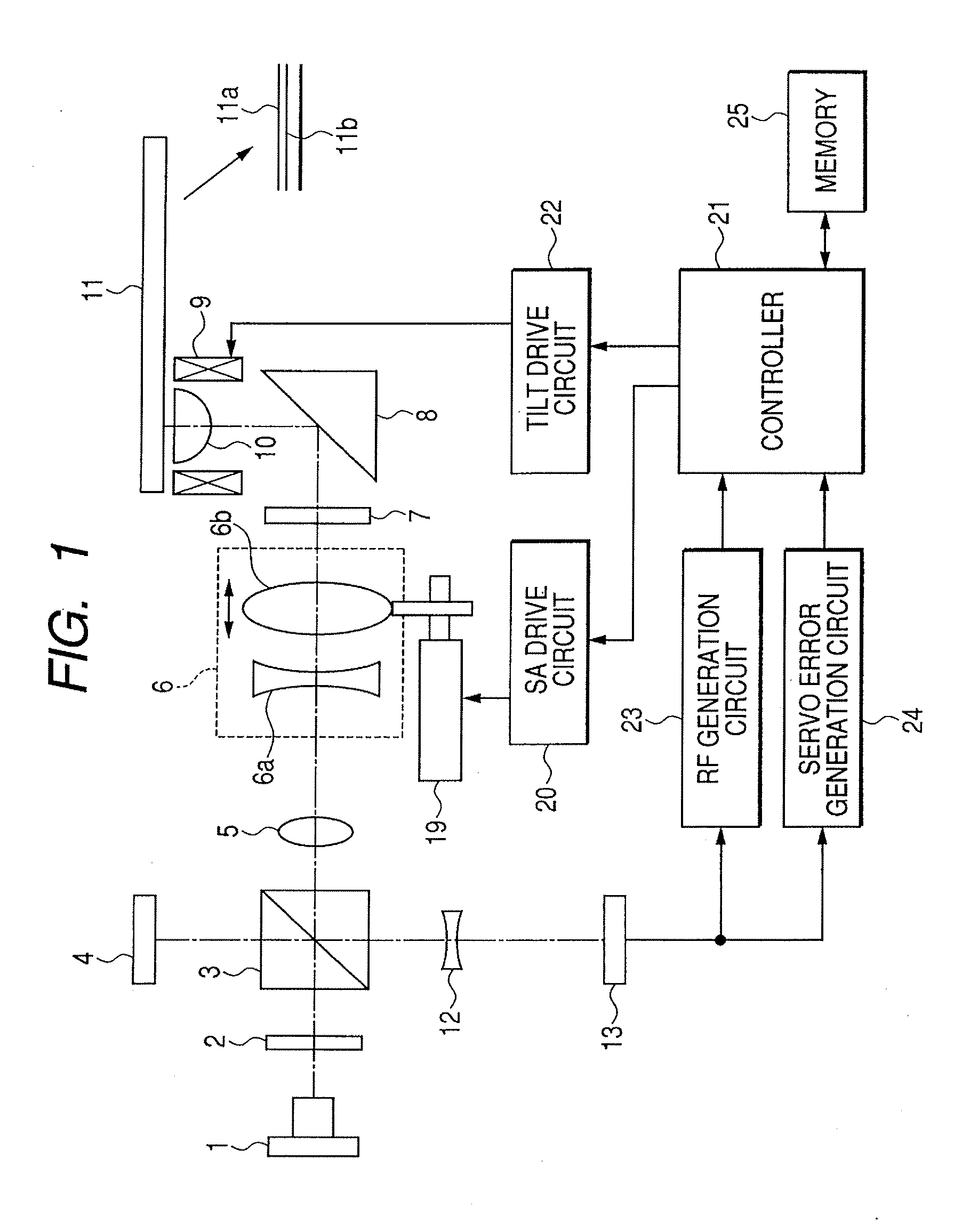
[0032]FIG. 1 is a block diagram illustrating a first embodiment of an optical information recording and reproducing apparatus according to the present invention. In the figure, a semiconductor laser 1 as a light source has a wavelength of, for example, 405 nm. An optical disc 11 as an information recording medium is a two layer disc having a first layer 11a and a second layer 11b as recording layers as illustrated in FIG. 1. The second layer 11b is on the side of incident light, and has a transmission layer thickness of 70 μm. The first layer 11a is a recording layer opposite to the side of incident light, and has a transmission layer thickness of 100 μm.
[0033] Reference numerals 2, 3, 4, and 5 designate a diffraction grating, a polarized light beam splitter, a sensor for a front monitor, and a collimator lens, respectively. A light beam expander 6 is used for correcting spherical aberration and is formed of a concave lens 6a and a convex lens 6b.
[0034] The convex lens 6b of the t...
second embodiment
[0070] Next, a second embodiment according to the present invention is described. The structure of the second embodiment is similar to the one illustrated in FIG. 1, and a method of detecting a servo error signal and the like are similar to those in the first embodiment, and thus, detailed description thereof is omitted. This embodiment simplifies optimization of the amount of objective lens tilt.
[0071] As apparent from FIG. 8, by making the amount of tilt of the objective lens in the second layer 11b of the optical disc 11 0.45 times as much as that of the first layer 11a, coma aberration can be substantially completely corrected, and, even when the disc is tilted by 0.6 degrees or more, coma aberration is within 8 mλrms. Therefore, in this embodiment, by making the correction factor of the amount of tilt of the second layer 11b in relation to the first layer 11a of the optical disc 11, optimization of the amount of objective lens tilt of the second layer 11b is omitted.
[0072] Ne...
third embodiment
[0077]FIG. 9 is a block diagram illustrating an optical information recording and reproducing apparatus according to a third embodiment of the present invention. A method of detecting a servo error signal and the like are similar to those in the first embodiment illustrated in FIG. 1, but this embodiment differs from the first embodiment in that an optical tilt sensor 14 for detecting disc tilt is mounted on a fixed portion of an optical system. The tilt detection circuit 26 detects the amount of disc tilt based on a tilt signal of the optical tilt sensor 14. It should be noted that, in FIG. 9, like numerals are used to designate like or identical members illustrated in FIG. 1, and description thereof is omitted.
[0078] The semiconductor laser 1 has a wavelength of 405 nm. The first layer 11a and the second layer 11b of the optical disc 11 have substrate thicknesses of 100 μm and 70 μm, respectively. The NA of an objective lens 10 is 0.85 and is designed such that, when the transmis...
PUM
 Abstract
Description
Claims
Application Information
 - R&D
- Intellectual Property
- Life Sciences
- Materials
- Tech Scout
- Unparalleled Data Quality
- Higher Quality Content
- 60% Fewer Hallucinations
Browse by: Latest US Patents, China's latest patents, Technical Efficacy Thesaurus, Application Domain, Technology Topic, Popular Technical Reports.
© 2025 PatSnap. All rights reserved.Legal|Privacy policy|Modern Slavery Act Transparency Statement|Sitemap|About US| Contact US: help@patsnap.com


