Heat-assisted thin-film magnetic head and heat-assisted magnetic recording method

Active Publication Date: 2010-01-28
TDK CORPARATION
View PDF4 Cites 13 Cited by
  • Summary
  • Abstract
  • Description
  • Claims
  • Application Information

AI Technical Summary

Benefits of technology

[0015]It is therefore an object of the present invention to provide a thin-film magnetic head, which can form stable recording bits pattern having steep magnetization transition regions without using a near-field light generating element, a head gimbal assembly (HGA) having the thin-film magnetic head, and an recording apparatus having the HGA.
[0016]Further, it is also an object of the present invention to provide a heat-assisted magnetic recording method, which can form stable recording bits pattern having steep magnetization transition regions without using a near-field light emission.
[0019]Using the thin-film magnetic head, magnetization transition regions of recording bits formed on the magnetic recoding medium are eventually decided at the trailing side cross point of the projecting region, where the gradient of the magnetic field is very big. Thus, magnetization transition regions become steep, and it is possible to make recording bits smaller and to achieve a high line recording density. Moreover, recording bits are not exposed to high temperature after writing. As a result, magnetizations of recording bits are stable, and it may contribute to improve the signal to noise ratio. As explained above, it is possible to form stable recording bits pattern, which have precipitous magnetization transition regions, without using the near-field light generating element, and it contributes to improve both line recording density and signal to noise ratio.
[0020]Favorably, a value EHXP of the write magnetic field at a trailing side cross point on the projecting region of the write magnetic field profile and the anisotropy field profile satisfies a relation of 0.2(EHMAX−EHMIN)<=EHXP−EHMIN<=0.8(EHMAX−EHMIN), where EHMIN is the minimum write magnetic field value of a flat region of the write magnetic field profile, and EHMAX is the maximum write magnetic field value of the projecting region. This improves the signal to noise ratio steadily. Advantageously, the minimum anisotropy field value HKMIN of the anisotropy field profile satisfies a relation of HKMIN>EHMIN. With this configuration, it is possible to prevent the adjacent track erasure (ATE), which unintentionally erases the data of adjacent tracks.

Problems solved by technology

However, thermal stability of the magnetization of recording bits is degraded by decreasing the size of magnetic microparticles.
However, increment of the energy KU causes increment of a coercive force of magnetic recording media.
Therefore, heads cannot write data to magnetic recording media when the coercive force of media exceeds the maximum limit of the write magnetic field.
However, following problems arise to realize heat-assisted magnetic recording using a near-field light generating element such as the near-field light probe described above.
As a result, the near-field light generating element, which is provided at the end surface of the waveguide, cannot be placed close enough to the main magnetic pole.
In this case, recording bits can be damaged, because magnetization transition regions of recording bits are disturbed by receiving a higher write magnetic field after writing, in addition to the difficulty of shortening the distance between the near-field light generating element and the main magnetic pole.
However, this structure does not include a main magnetic pole, and an applicable write magnetic field is limited.
Moreover, it is difficult to realize the near-field light generating element with enough generating efficiency so far, in addition to problems listed above.
Especially, the generating efficiency is not enough to supply the appropriate heat to the magnetic recording medium, which rotates high speed, for example approximately 7200 rpm.
However, it is not possible to realize the good heat-assisted magnetic recording by just using a light supplying unit, which can supply a light with a big spot diameter.
For example, in case the light supplying unit, which can supply the light with a big spot diameter, is placed on the trailing side with reference to the main magnetic pole, recording bits may be damaged, because magnetization transition regions of recording bits are disturbed by being exposed to higher temperature after writing.
On the other hand, in case the light supplying unit is placed on the leading side with reference to the main magnetic pole, magnetization transition regions of recording bits are eventually decided under the condition that gradients of both the magnetic field and the temperature are small, and therefore it is very difficult to achieve a high line recording density.

Method used


Image

  • Heat-assisted thin-film magnetic head and heat-assisted magnetic recording method
  • Heat-assisted thin-film magnetic head and heat-assisted magnetic recording method
  • Heat-assisted thin-film magnetic head and heat-assisted magnetic recording method

Examples


example

[0099]As the example, the magnetization state of recording bits pattern was simulated, in case of the heat-assisted magnetic recording of 2100 kFCI (Flux Change per Inch) line recording density. Further, the signal to noise ratio SNR of an output from the MR element 33 is calculated when the MR element 33 reads the recording bits pattern.

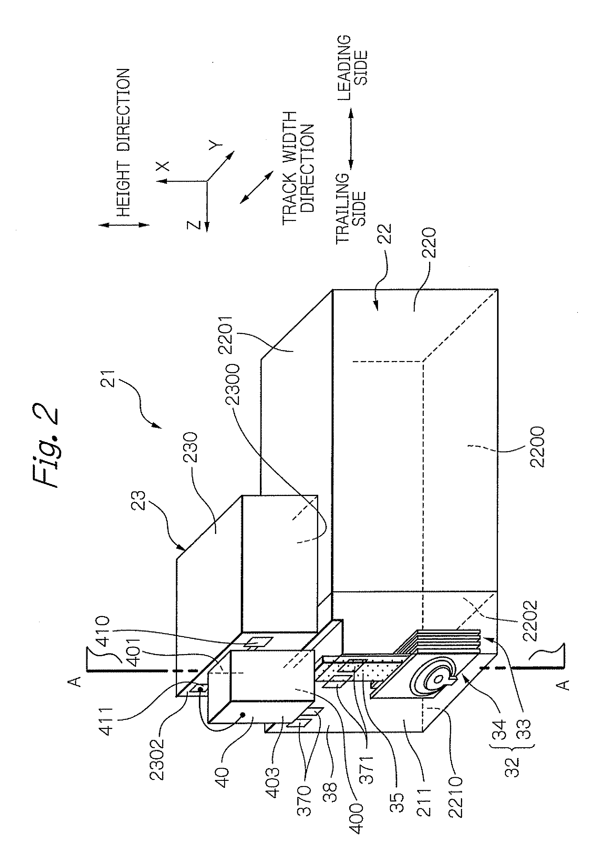
[0100]For the simulation of the magnetization state, LLG simulation according to Landau-Lifshitz-Gilber equation was used. For the condition of the simulation, the power of the laser source for heat-assisted was 8 mV. The wavelength of the laser light was 650 nm. The spot diameter of the laser light from the waveguide 35 was 800 nm. Moving line velocity of the rotation of the disk 10 was 1.5 m / s. The magnetic spacing, which is a distance between the recording layer surface and end surface of both the MR element 33 and the electromagnetic transducer 34, was 6 nm. Further, the thickness TP of the fore end part of the main magnetic pole 3400 was 0.3 μm...


PUM


Abstract

In a heat-assisted magnetic recording, a thin-film magnetic head, which can form stable recording bits pattern having steep magnetization transition regions without using a near-field light generating element, is provided. The head is formed on an element forming surface of a substrate, and has a waveguide for leading a light for heat-assist to a magnetic medium and a write element formed on a trailing side of the waveguide and having a magnetic pole for applying a write field to the medium. Here, a write field profile, which is an intensity distribution of the write field from the pole along a track in a recoding layer of the medium, has a projecting region on a leading side. Further, an anisotropy field profile, which is a distribution of an anisotropy field when the anisotropy field is reduced by irradiating the light on a part of the recoding layer, traverses the projecting region.

Description

BACKGROUND OF THE INVENTION[0001]1. Field of the Invention[0002]The present invention relates to a heat-assisted magnetic recording method, which performs magnetic recording by irradiating a light to a magnetic recording medium to reduce an anisotropy field of the magnetic recording medium, and a thin-film magnetic head, which writes data using the heat-assisted magnetic recording method.[0003]2. Description of the Related Art[0004]With increasing recording density of magnetic disk drive apparatuses, it is required to improve the performance of thin-film magnetic heads. Composite-type thin-film magnetic heads, which have a stacked structure of a magnetoresistive (MR) element for reading data signals and an electromagnetic transducer for writing data signals, are widely used as such thin-film magnetic heads.[0005]Generally, magnetic recording media are magnetically discontinuous, in which magnetic microparticles are gathered together, and each of magnetic microparticles has a single ...

Claims


Application Information

Patent Timeline
IPC IPC(8): G11B5/02G11B5/33G11B5/48
CPCG11B5/314G11B2005/0021G11B2005/0005G11B5/4866
Inventor SHIMAZAWA, KOJIMIYAUCHI, DAISUKEKURIHARA, KATSUKI
Owner TDK CORPARATION
Why Eureka
Try Eureka