Faraday Rotator, Optical Isolator, Polarizer, and Diamond-Like Carbon Thin Film

a technology of diamond-like carbon thin film and polarizer, which is applied in the field of faraday rotators, optical isolators, polarizers and diamond-like carbon thin films, can solve the problems of large overall size, high cost of faraday rotators, polarizers (analyzers), and noise produced by beams returning to light sources, so as to improve the performance of polarizers and reduce costs

Inactive Publication Date: 2007-05-10
SUMITOMO ELECTRIC IND LTD
View PDF4 Cites 2 Cited by
  • Summary
  • Abstract
  • Description
  • Claims
  • Application Information

AI Technical Summary

Benefits of technology

[0014] Given the foregoing, objects of this invention are: first, to miniaturize and hold down the cost of, respectively, Faraday rotators, polarizers, analyzers, magnetic bodies, and optical isolators in which these are the constituent elements; second, to enable a Faraday rotator and an optical isolator to handle a plurality of wavelengths; and third, a new material useful in miniaturizing and in lowering the cost and enhancing the performance of polarizers to begin with, and of various optical devices.
[0034] Accordingly, under this invention, miniaturizing and moreover holding down the costs of Faraday rotators, polarizers, analyzers, magnetic parts, and optical isolators having these as their constituent elements, is made possible. Likewise, manufacturing Faraday rotators and optical isolators that can handle plural wavelengths is made possible. Furthermore, a new material useful in miniaturizing and in lowering the cost and enhancing the performance of polarizers to begin with, and of various sorts of optical devices, can be provided.

Problems solved by technology

Noise produced by beams returning to a light source—especially to a semiconductor laser—often turns out to be a major problem in designing optical communications systems and optical devices.
What is more, with conventional isolators especially—whose basic constituent elements are a Faraday rotator, a polarizer (analyzer) and a magnetic part—has been the problem of being large-sized overall.
Meanwhile, Faraday rotators, polarizers (analyzers) and magnetic bodies are expensive, making conventional optical isolators in which these are the constituent elements cost all the more.
A further problem has been that because the individual constituent elements in conventional optical isolators are independent, their assembly process is complex, adding that much more to the cost.
The consequent problem too with conventional optical isolators having a conventional Faraday rotator as a constituent element has been that they basically can handle only a single wavelength.

Method used


Image

  • Faraday Rotator, Optical Isolator, Polarizer, and Diamond-Like Carbon Thin Film
  • Faraday Rotator, Optical Isolator, Polarizer, and Diamond-Like Carbon Thin Film
  • Faraday Rotator, Optical Isolator, Polarizer, and Diamond-Like Carbon Thin Film

Examples


embodiment 1

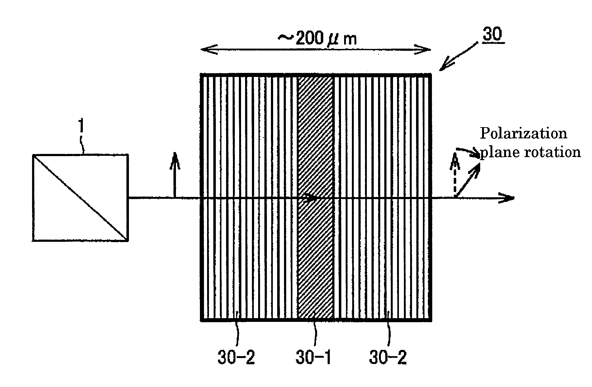
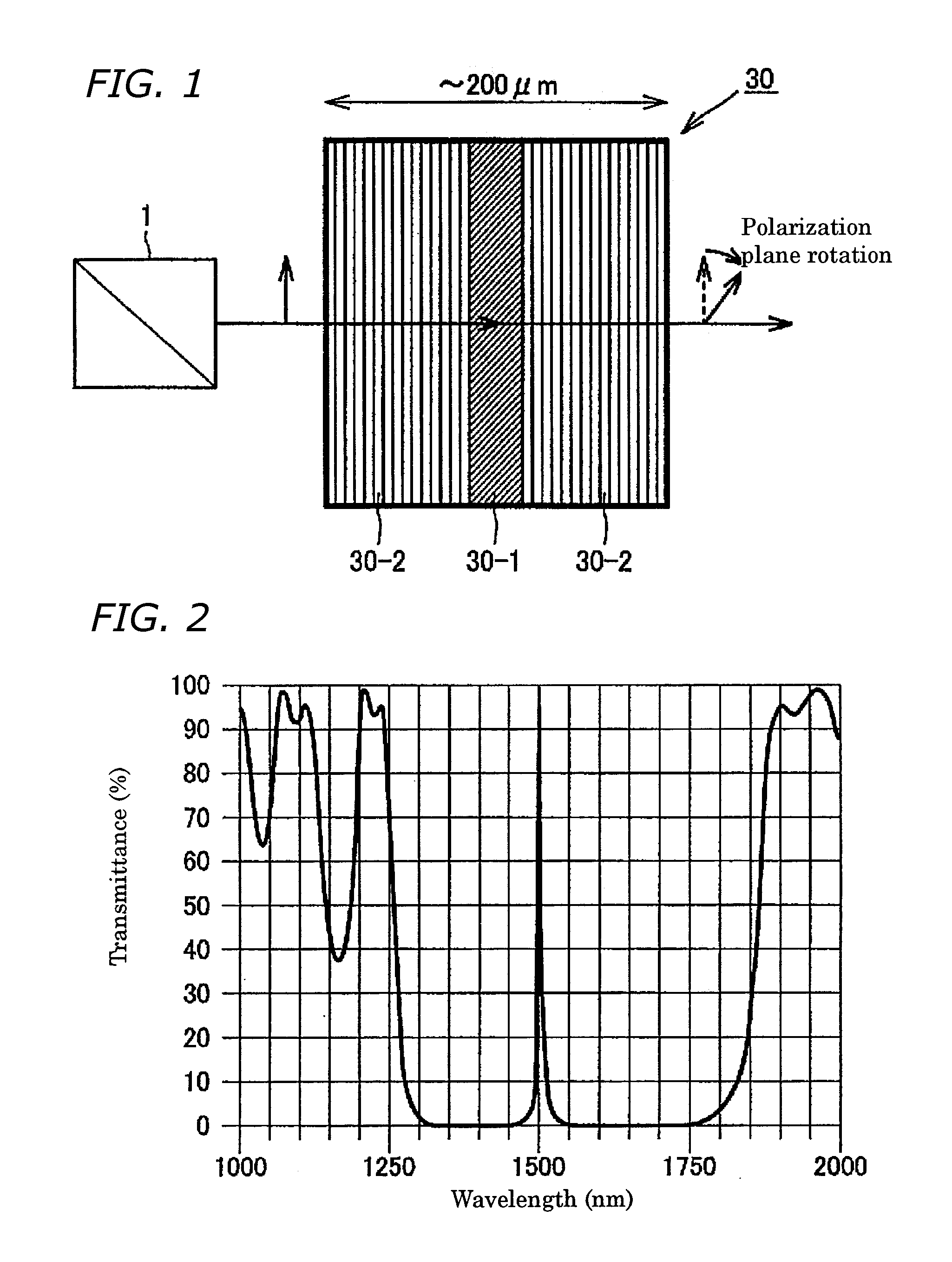
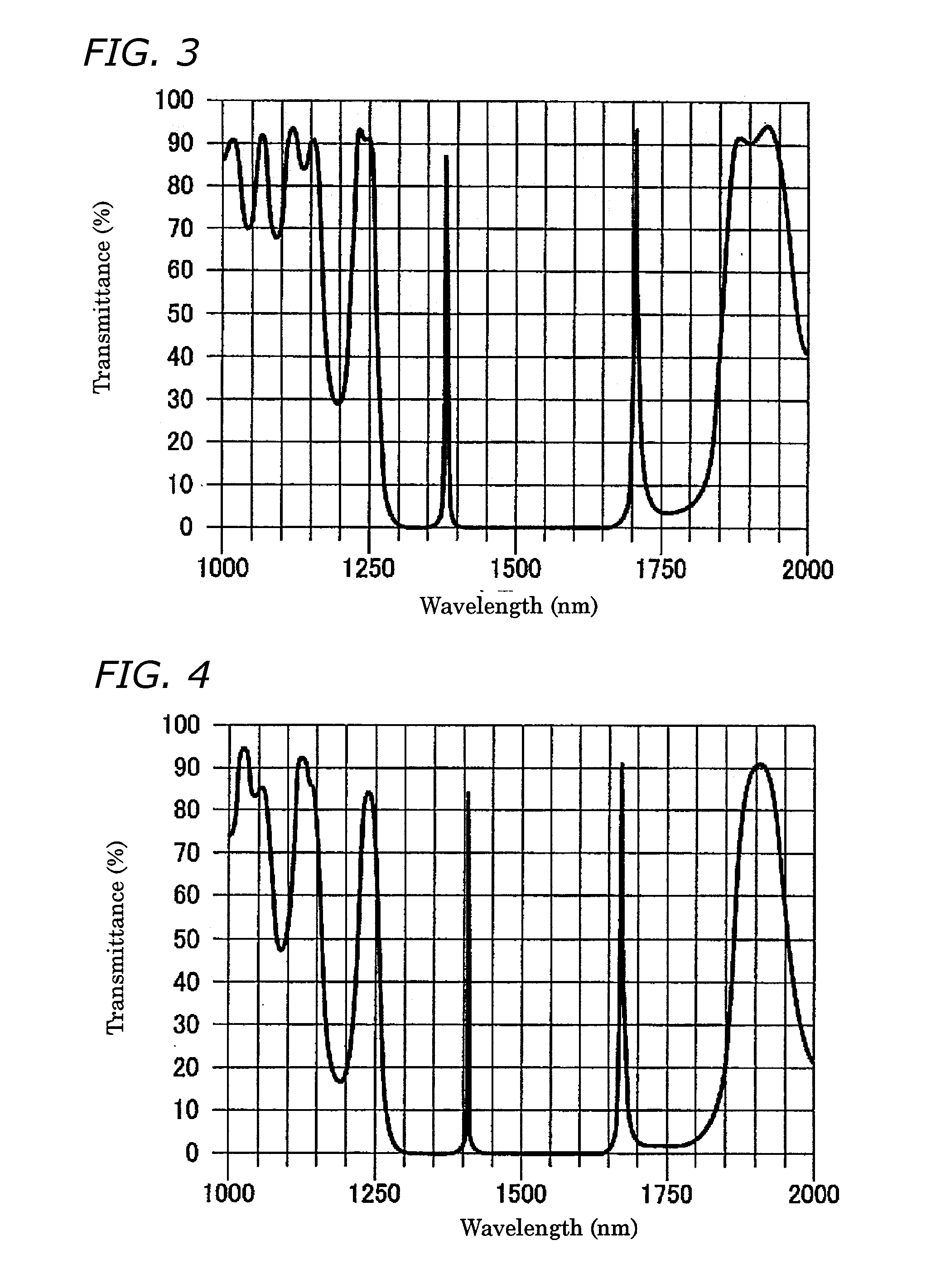
[0051]FIG. 1 is a view schematically illustrating a Faraday rotator of Embodiment 1 according to the invention.

[0052] This Faraday rotator 30 is furnished with, as shown in FIG. 1, a magneto-optical part 30-1 for rotating the polarization plane of incident light traveling in the direction of its magnetic field, and dielectric multi-layer films 30-2 for localizing within the magneto-optical part 30-1 incident light of at least one wavelength.

[0053] The magneto-optical part 30-1 is constituted from a gadolinium iron garnet (GIG hereinafter) thin film, and the dielectric multi-layer films 30-2 are composed by laminating in alternation silicon dioxide as a low refractive-index layer, and titanium dioxide as a high refractive index layer.

[0054] As shown in FIG. 1, the Faraday rotator 30 is constituted by arranging the dielectric multi-layer films30-2 on either side of the magneto-optical part 30-1 to create a resonant structure. The resonant structure of the dielectric multi-layer fil...

embodiment 2

[0080]FIGS. 8 and 9 are views schematically illustrating optical isolators of Embodiment 2 according to the invention.

[0081] Optical isolator 60a in FIG. 8 is constructed by arranging a polarizer 20 and an analyzer 40 on either side of the Faraday rotator depicted in Embodiment 1, and further arranging magnetic parts 5 along the top and bottom.

[0082] As explained in setting out Embodiment 1, the Faraday rotator 30 functions to selectively rotate only the polarization plane of incident light of a given wavelength(s). This enables optical isolator 60a incorporating the Faraday rotator 30 to selectively block only the return beams from the incident light of the given wavelength(s).

[0083] The polarizer 20 and the analyzer 40 can be constituted by irradiating a diamond-like carbon (DLC hereinafter) thin film along a bias with either a particle beam or an energy beam. (Details of a polarizer (analyzer) constituted using the DLC thin film will be described in Embodiment 3.)

[0084] Accor...

embodiment 3

[0088]FIG. 10 is a view schematically illustrating a manufacturing process of a polarizer according to Embodiment 3 of the invention.

[0089] The polarizer is characterized in being formed by irradiating a DLC thin film 11 along a bias with either a particle beam or an energy beam. Although ion beams, electron beams, proton beams, α-rays and neutron beams are conceivable particle beams, and light rays, x-rays and γ-rays are conceivable energy beams, taking the example herein of irradiating with ion beams, a method of lending a refractive index distribution to the DLC thin film will be explained with reference to FIG. 10.

[0090] As indicated in FIG. 10, at first a mask 12 that is a transcription of a refractive-index distribution pattern is adhered atop the DLC thin film. From above the mask 12, oblique irradiation is performed with a beam of helium or argon ions, for example. The refractive index of the portions as at 11-1 receiving ion-beam irradiation through the transmitting areas...


PUM

PropertyMeasurementUnit
in-plane thicknessaaaaaaaaaa
wavelengthaaaaaaaaaa

Abstract

A diamond-like carbon (DLC) film having refractive indices distributed in a pattern oriented within the plane of the film or on a bias with respect to the thickness of the film. Such films may be useful in low-cost Faraday rotators, in polarizers (analyzers), and in magnetic substances, and in Faraday rotators and optical isolators that can handle a plurality of wavelengths. The refractive index structure may be imparted to the DLC film, for example, by irradiating at least one region of the film with either a particle or energy beam.

Description

BACKGROUND OF THE INVENTION [0001] 1. Technical Field [0002] The present invention relates to Faraday rotators, optical isolators, polarizers and diamond-like carbon thin films, and more particularly relates to—in optical communications fields—Faraday rotators for rotating light-wave polarization planes, optical isolators for blocking return beams from a light source, polarizers for transmitting only a given polarized component of light, and to diamond-like carbon thin films utilized as materials in optical communications fields. [0003] 2. Description of the Related Art [0004] In optical communications systems constituted from optical fibers and optical elements, reflected light from optical-connector junctions and optical circuit components is sometimes reintroduced to the light source. Noise produced by beams returning to a light source—especially to a semiconductor laser—often turns out to be a major problem in designing optical communications systems and optical devices. [0005] ...

Claims


Application Information

Patent Timeline
Patent Type & Authority Applications(United States)
IPC IPC(8): G02B1/10G02B5/28G02B5/30G02B27/28G02F1/09
CPCG02B1/02G02F1/093G02F1/09G02B1/12
Inventor OKUBO, SOICHIROMATSUURA, TAKASHI
Owner SUMITOMO ELECTRIC IND LTD
Why Eureka
Try Eureka