
Envelope for mailing of cards containing an embedded chip

Inactive Publication Date: 2007-05-10
THE DIRECTV GROUP +1
View PDF10 Cites 2 Cited by
  • Summary
  • Abstract
  • Description
  • Claims
  • Application Information

AI Technical Summary

Benefits of technology

[0018] It is therefore an object of the present invention to provide an improved envelope utilizing a specific means to keep the card intact and to prevent damage to the computer chip and the card as it is processed through mail sorting equipment.
[0019] It is a further object of the present invention to provide an improved design to an envelope which can be processed through flat automated sorting equipment without damage to the contents thereof.
[0020] A still further object of this invention is to provide a lightweight envelope which allows for the processing of the envelope through standard postal sorting equipment but meets the requirement of having a weight of one ounce or less.

Problems solved by technology

These cards are generally mailed to the consumer using national postal systems and it has been found that the standard mailing sorting equipment damages the card when the letter containing the card is processed therethrough.
As a result, the consumer receives a damaged card which is not usable and must go back to the issuer of the card for a replacement card thereby significantly increasing the costs of distribution of the cards and the time delay occurring from the card leaving the distributor to the consumer.
This has significantly increased the cost of the distribution process and increased the delays in the consumer receiving the required card.
The potential use for smart card technology is limitless.
The processing of a letter containing a smart card through standard mail sorting equipment has resulted in damage to the card.
This damage includes physical damage to the computer chip.
The damage is caused by the flexing of the card as it is processed through the postal sorting equipment.
However, the gum or the adhesive strip may not always retain the contents in the desired position.

Method used


Image

  • Envelope for mailing of cards containing an embedded chip
  • Envelope for mailing of cards containing an embedded chip
  • Envelope for mailing of cards containing an embedded chip

Examples


Embodiment Construction

[0025] This invention relates to mailing envelopes and in particular, to a mailing envelope used for mailing of a rigid module that is embedded in a plastic or non-plastic substrate commonly referred to as a card.

[0026] The envelope has a unique glue design of a false bottom using paper of a specified quality and weight. The envelope design and paper quality selected provide it with sufficient strength for use with high speed insertion equipment. The envelope is also light enough that with card and insertions, the resulting letter weighs one ounce or less.

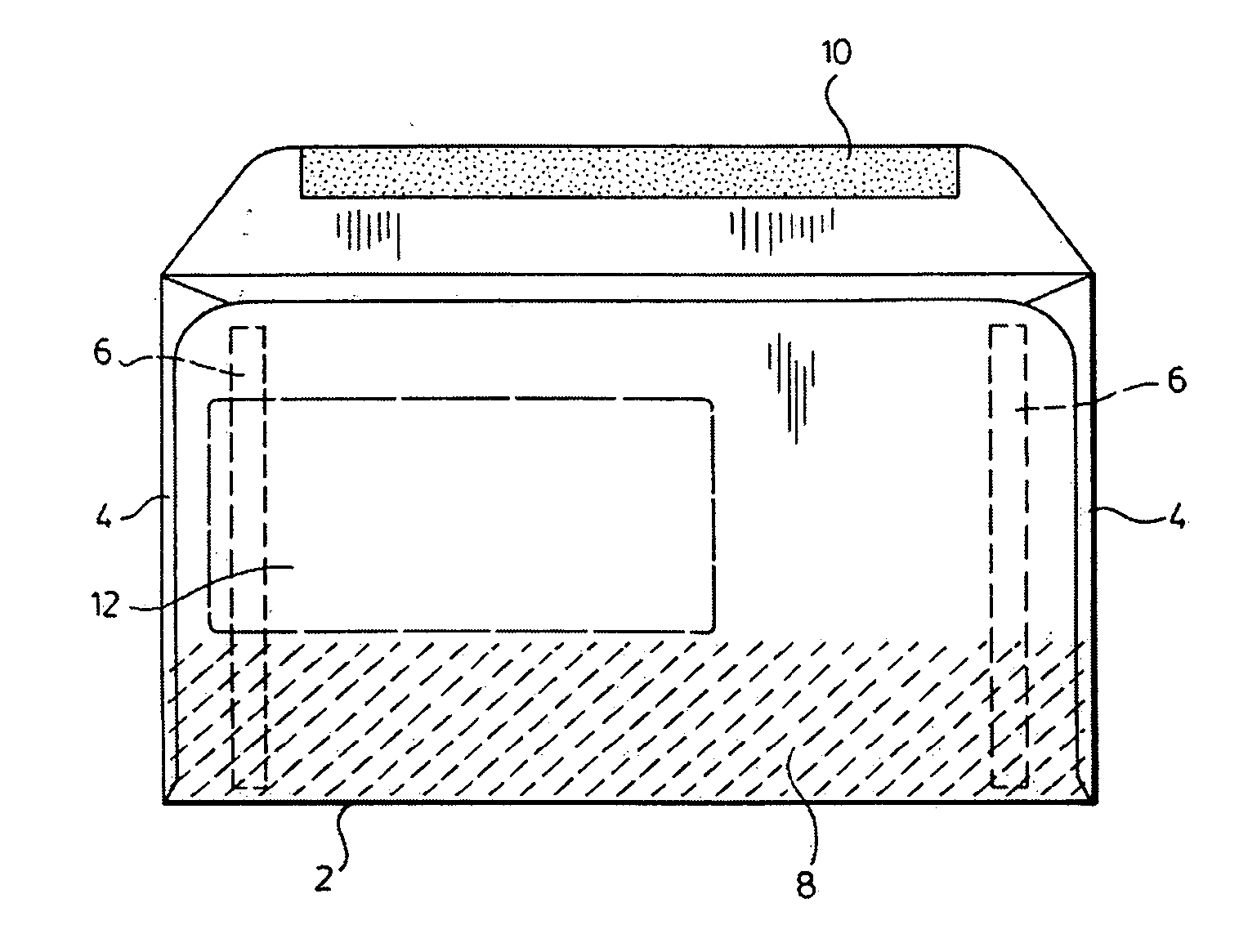
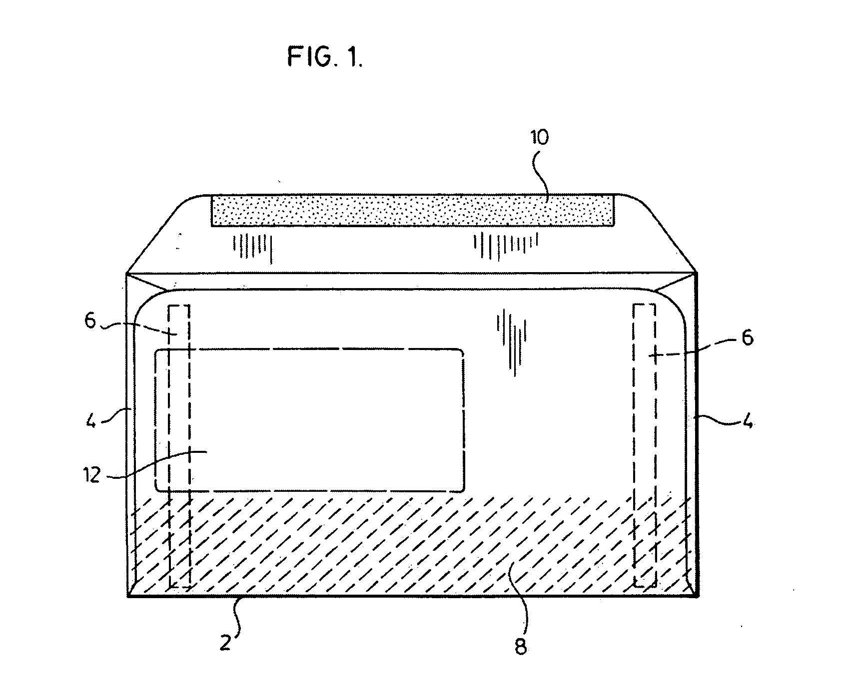
[0027]FIG. 1 shows the back side of an envelope. In manufacturing the envelope, side flaps 4, 4 are provided which in the preferred embodiment, have a minimum one inch width.

[0028] Glue lines 6, 6 are provided on each side and the gluing on the side flaps extends to the side edge immediately below the top edge to immediately below the bottom edge. In this manner, no glue is exposed.

[0029] A false bottom 8 is provided on the env...


PUM


Abstract

A new mailing envelope for use in mailing of a rigid module that is embedded in a plastic or non-plastic substrate.

Description

FIELD OF THE INVENTION [0001] The present invention relates generally to envelopes. More particularly, the present invention relates to a new mailing envelope for use in mailing of a rigid module that is embedded in a plastic or non-plastic substrate. BACKGROUND OF THE INVENTION [0002] The use of plastic or non-plastic substrates containing a rigid module embedded therein (hereinafter referred to as a card) is increasing exponentially. [0003] These cards are generally mailed to the consumer using national postal systems and it has been found that the standard mailing sorting equipment damages the card when the letter containing the card is processed therethrough. As a result, the consumer receives a damaged card which is not usable and must go back to the issuer of the card for a replacement card thereby significantly increasing the costs of distribution of the cards and the time delay occurring from the card leaving the distributor to the consumer. This has significantly increased ...

Claims


Application Information

Patent Timeline
IPC IPC(8): B65D27/00
CPCB65D27/00
Inventor ASIMAKIS, CHRISTADMAN, ALANTORRES, PELEGRIN JR.APPLETON, WILLIAM J.
Owner THE DIRECTV GROUP
Learn More