Analytical multi-spectral optical detection system

Inactive Publication Date: 2007-05-03
ROCHE MOLECULAR SYST INC
View PDF9 Cites 40 Cited by
  • Summary
  • Abstract
  • Description
  • Claims
  • Application Information

AI Technical Summary

Benefits of technology

[0011] The present invention provides systems and methods for measuring fluorescence signals. The systems and methods of the present invention provide highly accurate fluorescent based measurements of liquid samples or solid surfaces such as nucleic acid or protein detection arrays. For example, the systems and methods of the present invention are particularly useful in polymerase chain reaction (PCR) systems, especially real-time, quantitative PCR systems used for medical diagnostics.
[0013] The optical system describe herein can scan solid surfaces and determine the quantitative amount of unique color emissions from a specified area. The most common example would be a spatially resolved micro-array in which chemistry is performed on the surface of a glass slide or in the well of a micro-titer plate. This optical system provides the same advantages over prior optical systems in that more dyes can be detected with greater accuracy.
[0018] According to another aspect of the present invention, a system for detection of induced light emission in a sample is provided. The system typically includes a sample container, an emission detector, and an excitation source configured to generate excitation light having a plurality of different discrete wavelengths. The sample container is positioned to receive excitation light directly from the excitation source, and the emission detector is positioned to receive emission light directly from the excited sample. In operation, the laser or multi-plex lasers provide excitation light to the sample container and the detector directly receives the emission light from the sample container. The emission detector may include one or more filters that remove scattered excitation light. The scattered light filters can be multi or single line. Filters to remove the scattered light can be placed in the optical system path, e.g., using a controlled mechanical device such as a servo motor. One advantage of this design is that the emission spectra transmitted to the detector can be controlled allowing for more sample fluorescent information to be gathered. Such an optical detection and analysis system may or may not use fiber optic fibers for the emission optical path and may or may not use fiber optic fibers for the excitation emission optical path.

Problems solved by technology

Each of these systems has drawbacks.
This results in reduced detection precision combined with higher manufacturing and service costs.
Another limitation of filter-based optical systems is their inability to detect all of the fluorescent dyes commonly used in e.g., medical diagnostic assays.
Currently, a filter-based optical system can only resolve seven dyes (or emission spectra) in a dye mixture.
The emission spectra overlaps of mixtures containing more than five dyes are difficult to correct for with mathematical algorithms and optical controls.
This limits the ability of filter-based optical systems to quantitatively detect the dyes in assays used for medical diagnostics.
Other consequences of filter-based optical systems are that the optical system cannot be easily adapted to correct for assay problems or to accommodate new dyes.
For example, if a medical diagnostic test produces false results with a patient sample, no additional information can be obtained from the optical system to compensate for the problem.
Fixed bandwidths also increase the costs and time required to upgrade such a system.
In addition, some filters may not be upgradeable as previous dyes may no longer work with the instrument.
This material can build up in the optical interfaces causing partial or complete occlusion of the light path.
This can produce incorrect results.
Fluorescent signal precision and accuracy are also susceptible to partial blockage of random wells.
Signal variations also produce more strain on the signal processing algorithm further reducing reliability.
Thermal control efficiency and uniformity also suffer due to the holes present in the thermal control block of these other designs.

Method used


Image

  • Analytical multi-spectral optical detection system
  • Analytical multi-spectral optical detection system
  • Analytical multi-spectral optical detection system

Examples


example

[0067] Fluorescent analysis data obtained from a prototype optical system according to the present invention.

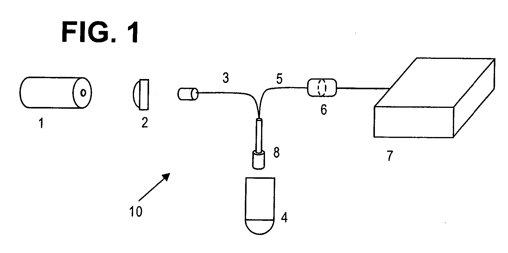
[0068] System Components Include:

Light SourcePartCenterTemperatureRMSPowerLaserDescriptionVendornumberWavelengthPowerControlNoiseStabilityClassDiodeCNIMBL-II473 nm10 mWThermoelectric   Class IIIbPumpedOptoelectronicsLaserTech. Co., Ltd,Changchun, ChinaDiodeWorld Star Tech,TECGL-532 nm10 mWThermoelectricClass IIIbPumpedToronto, ON,10LaserCanadaDiode LaserWorld Star TechTECRL-635 nm10 mWThermoelectricClass IIIb10G-635Detector OpticsLaser LineDescriptionVendorPart numberCenter WavelengthBlockingTransmissionTriple NotchSemrock,NF01-488 / 532 / 635-8-D488 nm, 532 nm8 O.D.>95%Laser Line FilterRochester633 nmNYDetectorGratingPartGrooveDescriptionVendornumberOptical DesignDetectorDensitySlit WidthSpecialDiffractionOceanHR2000Czerny-TurnerSony ILX511600 lines200 umSilverGradientOptics,2048-elementper inchCoatedSpectrophotoDunedinlinear CCDMirrorsmeterFLarray

[0069]FIG. 7 shows fluoresce...


PUM


Abstract

Analytical multi-spectral optical detection systems and methods. A light source provides one or multiple lines (e.g., discrete wavelengths) of high spectral purity excitation light that is optically coupled to a sample via delivery fiber optic cables. Emission light is collected and provided to an emission detector, such as a diffraction gradient spectrophotometer emission detector, using collection fiber optic cables bundled with the delivery fiber optic cables in a probe interface positioned proximal a sample holder. The probe interface may be scanned over one or more samples, or one or more samples may be scanned proximal a fixed interface probe. Multiple excitation wavelengths allows for simultaneous excitation and detection of multiple fluorescent dyes in the visible spectrum. This increases sample throughput and reduces signal variations associated with signal acquisition at different times. The optical system provides several advantages over other systems including higher sensitivity, improved compatibility with fluorescent dyes, better signal discrimination, increased system reliability and reduced manufacturing and service costs.

Description

BACKGROUND OF THE INVENTION [0001] The present invention relates generally to signal detection and analysis, and more particularly to multi-spectral fluorescent signal detection and analysis. [0002] Many systems exist today for exciting and detecting fluorescent signals in solid or liquid samples. Examples of such systems can be found in U.S. Pat. No. 6,015,674, U.S. Pat. No. 5,928,907 U.S. Pat. No. 6,713,297, US20020109844 A1, EP1080364 B1, and EP1080364 A1. [0003] Each of these systems has drawbacks. For example, the use of a plurality of fiber optic cables in U.S. Pat. No. 6,015,674A and U.S. Pat. No. 5,928,907A, and independent optics for each sample in U.S. Pat. No. 6,713,297 B2, US20020109844 A1, EP1080364 B1, and EP1080364 A1 increase the number of optical system components. Many commercial systems also use filters to control the light bandwidth which further increases the number optical components. This results in reduced detection precision combined with higher manufacturin...

Claims


Application Information

Patent Timeline
IPC IPC(8): G01N35/00
CPCG01N21/6428G01N21/645G01N21/6452G01N2021/6419G01N2021/6441
Inventor ELKIN, CHRISTOPHER J.HOOVER, WILLIAM M.KURNIK, RONALD T.
Owner ROCHE MOLECULAR SYST INC
Why Eureka
Try Eureka