
Process of producing ceramic matrix composites

a ceramic matrix and composite technology, applied in the field of ceramic matrix composite (cmc) articles, can solve the problems of affecting so as to improve the quality of ceramic matrix composites, and promote the effect of physical and mechanical properties

Inactive Publication Date: 2007-05-03
GENERAL ELECTRIC CO
View PDF13 Cites 26 Cited by
  • Summary
  • Abstract
  • Description
  • Claims
  • Application Information

AI Technical Summary

Benefits of technology

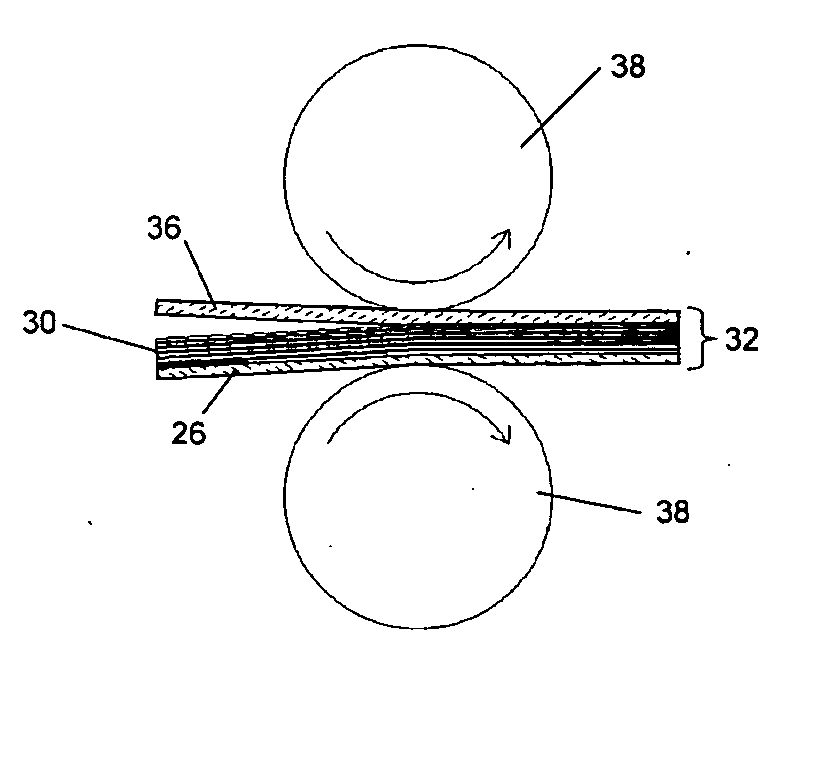
The present invention provides a process for producing CMC articles, such as components of gas turbine engines, that exhibit improved physical, mechanical, and microstructural properties. The process involves a drum winding process that promotes the physical and mechanical properties of a prepreg tape. This involves applying a first release sheet to a drum and then forming an impregnated tape that overlies the first release sheet. The impregnated tape is then passed through an apparatus that flattens the tape and redistributes the slurry mixture within the tape. This improves the uniformity of the matrix and fiber distribution in the tape, resulting in a more uniform tape thickness and shelf life. The process also allows for the use of fuzzy or damaged tows that would not be suitable if pre-impregnated with slurry before winding on the drum. This results in a more uniform distribution of fibers throughout the matrix and a higher fiber volume fraction in the prepreg tape.

Problems solved by technology

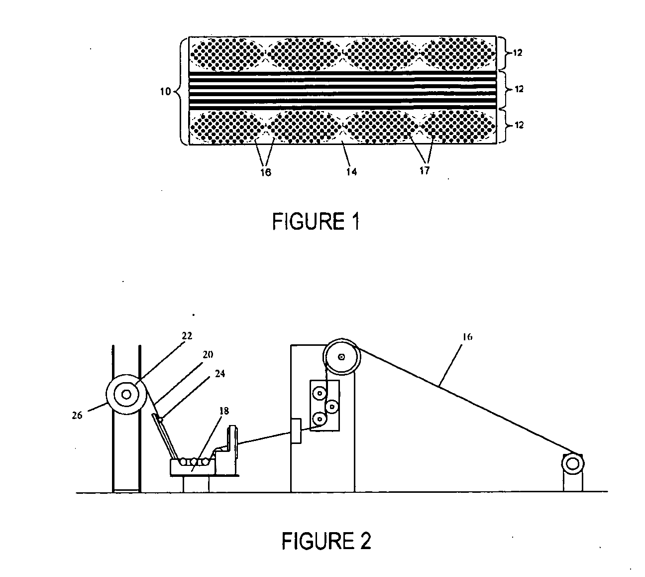
Because the pliability, or drapability, of the resulting prepreg tape is highly dependent on its residual solvent content, there is a limited time window from when a tape is wound to when the tape must be utilized in a composite preform lay-up.
For example, after about twelve hours at ambient conditions, tapes can become too stiff and lose tackiness to allow for a consistent lay-up of the composite plies.
Typical wet drum winding processes can also suffer from a significant amount of broken tow fibers and loosely adhering fibers (i.e., “fuzz”) that can break off and cause blockage of the orifice 24.
Another complication of conventional drum winding processes is that the tow 16 must be completely impregnated (i.e., wet out) with slurry during the winding process, which requires that the tow 16 spend a sufficient amount of time submersed in the slurry to allow for complete wet out.

Method used


Image

  • Process of producing ceramic matrix composites
  • Process of producing ceramic matrix composites
  • Process of producing ceramic matrix composites

Examples


Embodiment Construction

[0023] The present invention is generally applicable to CMC components, and particularly CFCC components. Notable examples of such components include combustor components, high pressure turbine vanes, and other hot section airfoils and components of gas turbine engines, though the invention has application to other components, including advanced power generation steam turbines and various other equipment that can make use of CMC components. Examples of CMC materials to which the invention pertains include those with a silicon carbide, silicon nitride and / or silicon reinforcement material in a ceramic matrix of silicon carbide, silicon nitride and / or silicon, e.g., a SiC / SiC CMC, though the invention also applies to other types of CMC materials. Examples of such materials and components are disclosed in commonly-assigned U.S. Pat. Nos. 6,024,898, 6,258,737, and 6,503,441, the contents of which relating to CMC materials and processing steps are incorporated herein by reference.

[0024]...


PUM

PropertyMeasurementUnit
thicknessaaaaaaaaaa
thicknessaaaaaaaaaa
thicknessaaaaaaaaaa

Abstract

A process for producing CMC articles, such as turbine components. The process entails applying a release sheet to a drum and then forming on the drum an impregnated tape that overlies the release sheet. The tape comprises a slurry mixture containing a ceramic precursor material and a unidirectionally-oriented filamentary material that may be wound onto the drum dry or already impregnated with the mixture. A second release sheet may be applied to overlie the tape. Alternatively, the filamentary material may be impregnated with the slurry mixture after it has been wound and removed from the drum. The resulting laminate structure may then be passed through an apparatus that flattens the tape and redistributes the slurry mixture within the tape.

Description

[0001] This invention was made with Government support under Agreement No. DE-FC02-92CE41000 awarded by the Department of Energy. The Government has certain rights in the invention.BACKGROUND OF THE INVENTION [0002] The present invention generally relates to ceramic matrix composite (CMC) articles. More particularly, this invention is directed to a process of producing melt-infiltrated (MI) CMC articles that includes processing steps capable of yielding prepreg tapes with improved physical and mechanical properties, thereby enabling the production therefrom of CMC articles that exhibit improved physical, mechanical, and microstructural properties. [0003] Higher operating temperatures for gas turbine engines are continuously sought in order to increase their efficiency. Though significant advances in high temperature capabilities have been achieved through formulation of iron, nickel and cobalt-base superalloys, alternative materials have been investigated. Notable examples include c...

Claims


Application Information

Patent Timeline
Patent Type & Authority Applications(United States)
IPC IPC(8): B29C33/58B28B3/00C04B33/32B28B1/00B28B5/00C04B35/64C04B33/36
CPCB28B1/40B28B23/0006B29C37/0075C04B35/565C04B35/62868C04B35/62871C04B35/62873C04B35/62884C04B35/62894C04B35/806C04B2235/386C04B2235/421C04B2235/422C04B2235/428C04B2235/5268C04B2235/60C04B2235/616C04B2235/6562C04B2235/96C04B2237/365C04B2237/38C04B35/80
Inventor MCGUIGAN, HENRY CHARLESCORMAN, GREGORY SCOT
Owner GENERAL ELECTRIC CO
Learn More