
Automatic channel switching method for low-power communication devices

a channel switching and automatic technology, applied in the field of automatic channel switching methods and algorithms for low-power wireless sensing devices, can solve the problems of significant difference in device communication efficiency and quality, generating undesirable energy consumption of management and acknowledgement messages/frames, and affecting the overall power consumption of the devi

Inactive Publication Date: 2007-04-26
SCOPRA SCI & GENIE SEC
View PDF21 Cites 56 Cited by
  • Summary
  • Abstract
  • Description
  • Claims
  • Application Information

AI Technical Summary

Benefits of technology

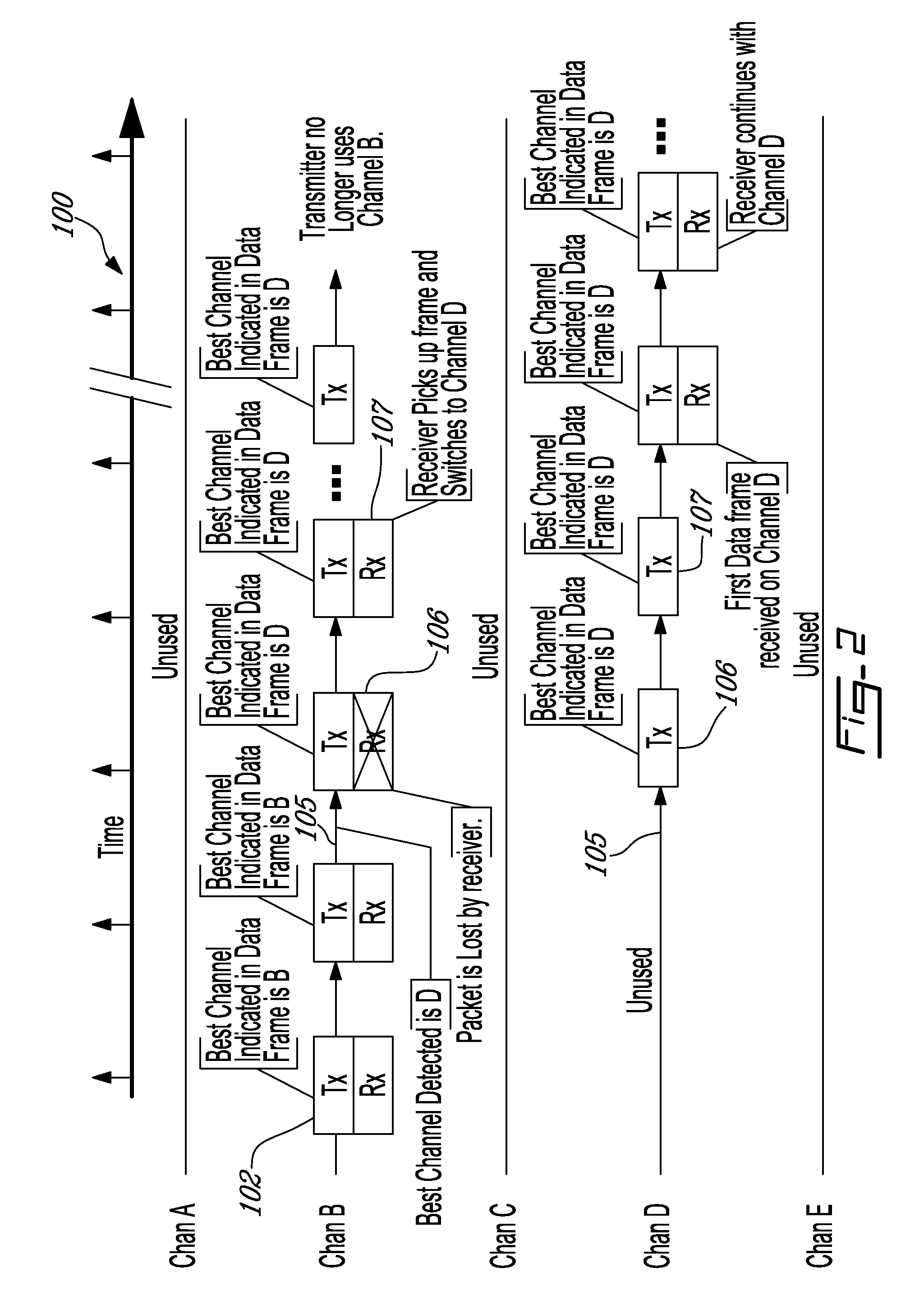
[0012] Also in accordance with the present invention, there is provided a transmitter for regularly transmitting data frames to a receiver via at least an active one of a plurality of wireless channels, the transmitter comprising circuitry adapted to monitor a quality of each of the channels to identify a best channel based on the quality and, wherein when the best channel is other than the active channel, providing an indicator representing the best channel in at least one subsequent data frame, sending the at least one subsequent data frame over the active channel and switching the active channel to the best channel for transmission of future data frames thereover.
[0013] Still in accordance with the present invention, there is provided a system for communicating data frames over at least an active one of a plurality of wireless channels, the system comprising a transmitter and a receiver, the transm

Problems solved by technology

For wireless devices configured to communicate over various allowable communication channels within a selected bandwidth, selection of a good communication channel, that is a channel on which communications experience limited noise and interference, can make a significant difference in the device's communication efficiency and quality and, ultimately, in the device's overall power consumption.
However, the transfer of such dedicated channel change control / management and acknowledgement messages / frames generates an undesirable consumption of energy, an important factor in low-power communication devices.

Method used


Image

  • Automatic channel switching method for low-power communication devices
  • Automatic channel switching method for low-power communication devices
  • Automatic channel switching method for low-power communication devices

Examples


Embodiment Construction

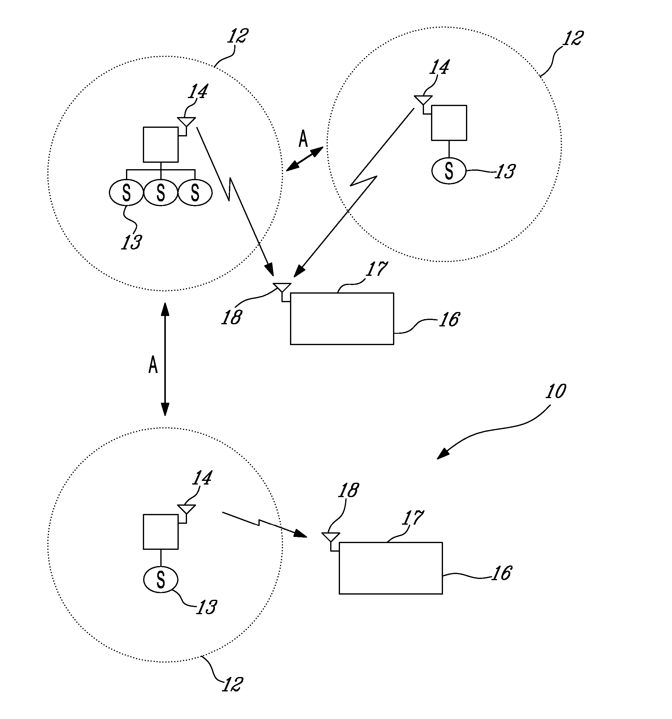
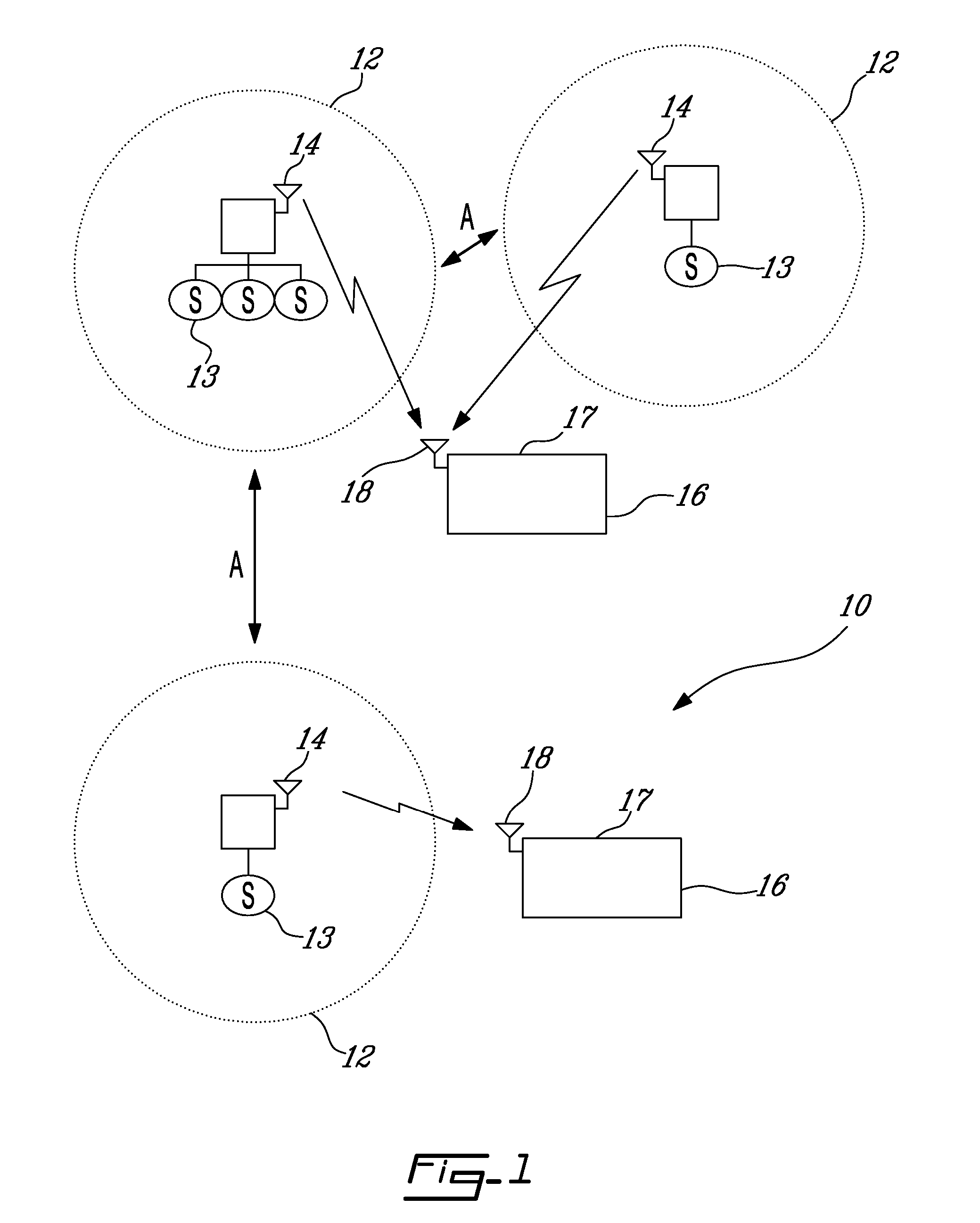
[0022] Referring to FIG. 1, and in accordance with an illustrative embodiment of the present invention, a physiological telemetry system, generally referred to using the numeral 10, will now be described. The system 10 is generally comprised of various sensing devices, as in 12, each comprising at least one sensor 13 communicatively coupled to a wireless transmitter / transceiver 14, for the wireless communication of sensed data to respective monitoring devices, as in 16.

[0023] The sensors 13 may include, but are not limited to, various types and combinations of physiological sensors such as oxymetry sensors, electrocardiogram (ECG) sensors, electroencephalogram (EEG) sensors, arterial pressure (AP) sensors, and the like. In the illustrative system 10, the sensors 13 are fitted to different patients, or again to animals in a veterinary setting, to measure and monitor various physiological parameters in order to diagnose various patient conditions and provide adequate treatment for th...


PUM


Abstract

A method allows the transmitter to change transmission to a better channel in order to minimize transfer interference. In general, the transmitter will monitor all RF channels and tag the data frames with a preferred channel ID. Upon reception of a tag within a given data frame indicating a change in preferred transmission channel, the receiver will commence listening on the new channel. To avoid transmission lapses, the transmitter may continue to transmit on the old channel for a predetermined amount of time or number of data frames to allow the receiver enough time to switch channels without losing any frames.

Description

CROSS-REFERENCE TO RELATED APPLICATIONS [0001] This applications claims priority on U.S. Provisional Application No. 60 / 727,867 filed on Oct. 19, 2005, the entire contents of which is incorporated herein by reference.FIELD OF THE INVENTION [0002] The invention relates to channel switching methods and algorithms in wireless communication systems and, more particularly, to an automatic channel switching method and algorithm for low-power wireless sensing devices in a physiological telemetry system. BACKGROUND OF THE INVENTION [0003] Communication devices, and particularly low-power wireless devices expected to operate efficiently for extended periods of time on a limited power source, are generally designed to communicate using enhanced data transfer protocols and algorithms configured to reduce power consumption and thus increase the operating lifetime of the device. For wireless devices configured to communicate over various allowable communication channels within a selected bandwid...

Claims


Application Information

Patent Timeline
IPC IPC(8): H04J3/14H04J1/16
CPCH04W72/082H04W72/085Y02D30/70H04W72/541H04W72/542
Inventor RICHARD, GUYNOEL, MICHELDUMONT, SYLVAIN
Owner SCOPRA SCI & GENIE SEC
Learn More