
Reduction of self-interference for a high symbol rate non-orthogonal matrix modulation

a non-orthogonal matrix, high symbol rate technology, applied in the direction of error prevention, digital transmission, diversity/multi-antenna systems, etc., can solve the problem of not achieving an increase in bit rate, and achieve the effect of reducing self-interferen

Inactive Publication Date: 2006-01-12
NOKIA CORP
View PDF15 Cites 146 Cited by
  • Summary
  • Abstract
  • Description
  • Claims
  • Application Information

AI Technical Summary

Benefits of technology

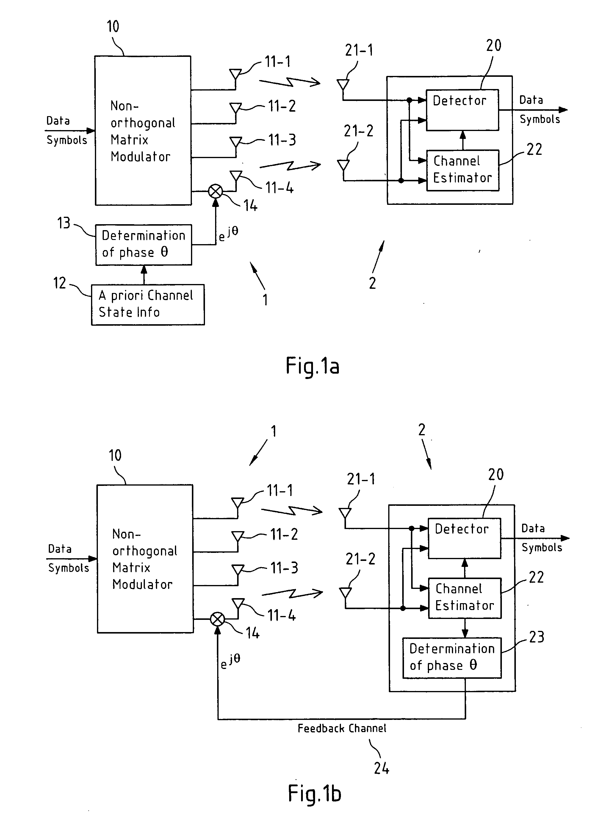
[0021] In view of the above-mentioned problems, it is now invented according to an embodiment of the present invention a method, a computer program, a computer program product, a system, a transmitter, a receiver and a module for reducing self-interference between data symbols that are modulated via a non-orthogonal matrix modulation with a symbol rate larger than 1.
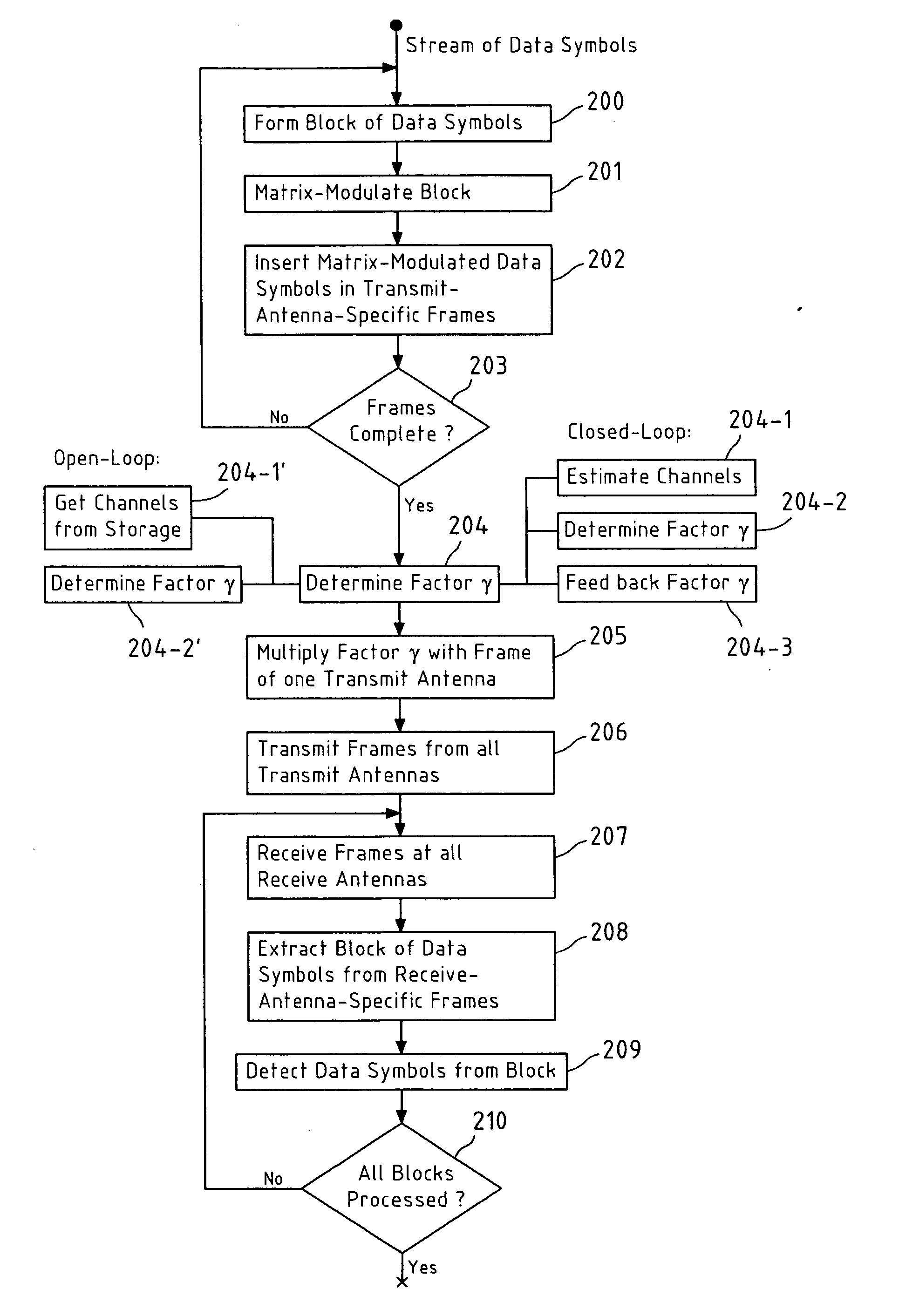
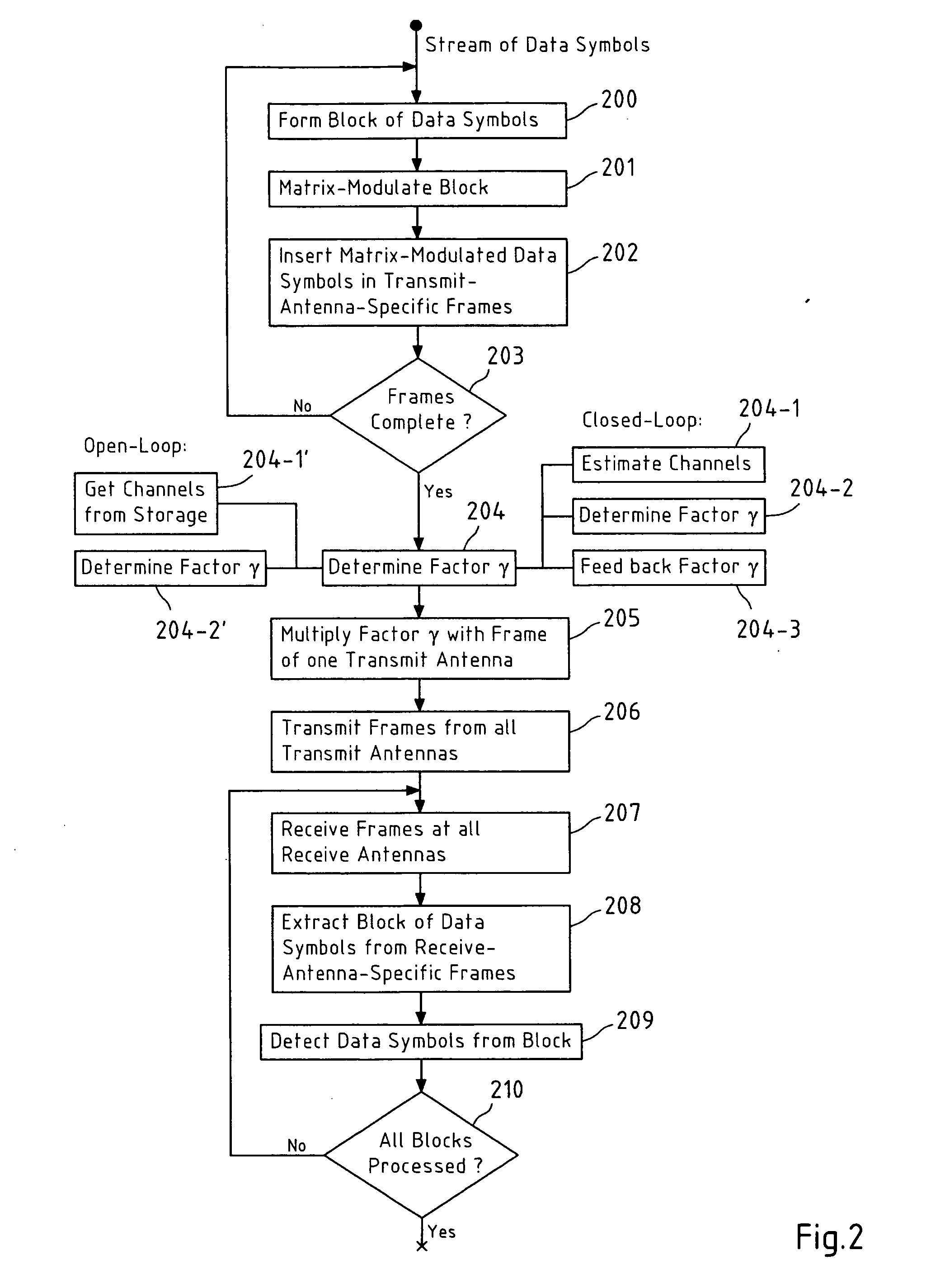
[0022] A method is proposed for reducing self-interference between at least four data symbols that are modulated via a non-orthogonal matrix modulation and transmitted from at least four transmit antennas to at least one receive antenna, said method comprising mapping said at least four data symbols onto said at least four transmit antennas and two orthogonal transmission resources via said non-orthogonal matrix modulation, multiplying data symbols mapped to one of said at least four transmit antennas with a factor γ, wherein said factor γ is determined at least in dependence on the transmission channel characteristics from said at least four transmit antennas to said at least one receive antenna to reduce a self-interference between said at least four data symbols, and transmitting said mapped data symbols and said mapped and multiplied data symbols from said at least four transmit antennas to at least one receive antenna in said two orthogonal transmission resources.

Problems solved by technology

However, the existence of various transmission sub-channels due to the spatial diversity used at the transmitter and / or at the receiver site has a harmful outcome, namely the interference caused by the simultaneous transmission of different signals between the receiver and the transmitter.
However, even when self-interference is minimized, the ABBA matrix modulation scheme remains a symbol-rate-1 matrix modulation scheme, so that, in comparison to the symbol-rate-1 STTD matrix modulation scheme, no increase in bit rate is achieved.

Method used


Image

  • Reduction of self-interference for a high symbol rate non-orthogonal matrix modulation
  • Reduction of self-interference for a high symbol rate non-orthogonal matrix modulation
  • Reduction of self-interference for a high symbol rate non-orthogonal matrix modulation

Examples


Embodiment Construction

[0064] The present invention proposes to reduce the self-interference encountered in non-orthogonal matrix modulation with at least four transmit antennas and symbol rates equal to or larger than 2 symbols / time period by multiplying the data symbols mapped to one of said at least four transmit antennas by a factor γ that is properly determined to achieve this self-interference reduction. In the following, for illustrative purposes, the presentation will concentrate on closed-loop space-time matrix modulation. It should however be noted that the present invention lends itself for deployment in the context of all other orthogonal transmission resources such as frequency, polarization, codes or eigenmodes of a channel, and may equally well be applied in open-loop systems in which the factor γ is determined at the transmitter site.

[0065] As an example for the application of the present invention, the non-orthogonal DSTTD block code as defined in equation (9) will be considered. The equ...


PUM


Abstract

A method for reducing self-interference between at least four data symbols that are modulated via a non-orthogonal matrix modulation and transmitted from at least four transmit antennas to at least one receive antenna comprises mapping the at least four data symbols onto the at least four transmit antennas and two orthogonal transmission resources via the non-orthogonal matrix modulation, multiplying data symbols mapped to one of the at least four transmit antennas with a factor γ, wherein γ is determined at least in dependence on the transmission channel characteristics from the at least four transmit antennas to the at least one receive antenna to reduce a self-interference between the at least four data symbols, and transmitting the mapped data symbols and the mapped and multiplied data symbols from the at least four transmit antennas to at least one receive antenna in the two orthogonal transmission resources.

Description

FIELD OF THE INVENTION [0001] This invention relates to a method for reducing self-interference between at least four data symbols that are modulated via a non-orthogonal matrix modulation and transmitted from at least four transmit antennas to at least one receive antenna. BACKGROUND OF THE INVENTION [0002] Conveying information over a multiple input multiple output (MIMO) system with multiple antennas at both the transmitter and receiver site of the transmission channel benefits from a significant enhancement of the channel capacity. This crucial fact has motivated a wide area of research over the past decade in order to better exploit multi-antenna systems. [0003] However, the existence of various transmission sub-channels due to the spatial diversity used at the transmitter and / or at the receiver site has a harmful outcome, namely the interference caused by the simultaneous transmission of different signals between the receiver and the transmitter. In the remainder of this speci...

Claims


Application Information

Patent Timeline
IPC IPC(8): H04B7/02H04L1/06
CPCH04L1/0618
Inventor BONNET, JEROME
Owner NOKIA CORP
Learn More