
Lightweight composite armor

Inactive Publication Date: 2007-04-26
MKP STRUCTURAL DESIGN ASSOCS
View PDF3 Cites 48 Cited by
  • Summary
  • Abstract
  • Description
  • Claims
  • Application Information

AI Technical Summary

Benefits of technology

[0007] The present invention improves upon existing composite armor designs through the use of optimally shaped ceramic pellets and a web system for patterning the pellets, improving manufacturability, and providing additional structural reinforcement. The result is lightweight, composite hybrid structures for ballistic protection particularly suited to tactical ground vehicles.
[0008] The preferred embodiment is a combination of three major components: 1) an optimally designed web system that allows armor tiles to be attached to it and that can be easily integrated with existing vehicle structures; 2) an advanced composite armor unit using a patent-pending BTR (Bio-mimetic Tendon-Reinforced) material as the supporting structure; and 3) optimally placed “waiting materials” which can provide enhanced ballistic impact resistance, energy absorption capability and structural integrity. These “waiting materials” are structural members that are not active at the beginning of the ballistic impact, but become active when needed or the active members have failed.
[0015] 6. Ease of manufacture, maintenance and repair, and low life-cycle cost due to the fact that armor units can be installed and removed individually

Problems solved by technology

Military vehicles, in particular, are vulnerable to higher-potency weapons such as rocket-launched grenades and other projectiles.
Ballistic steel armor plates, while relatively inexpensive, add thousands of pounds to a vehicle, many of which were not designed to carry such loads.
This has resulted in numerous engine and transmission failures as well as problems with vehicle suspensions and brakes.
The additional weight reduces fuel efficiency and makes it impossible to carry additional personnel in the vehicle in case of emergency.

Method used


Image

  • Lightweight composite armor
  • Lightweight composite armor
  • Lightweight composite armor

Examples


Embodiment Construction

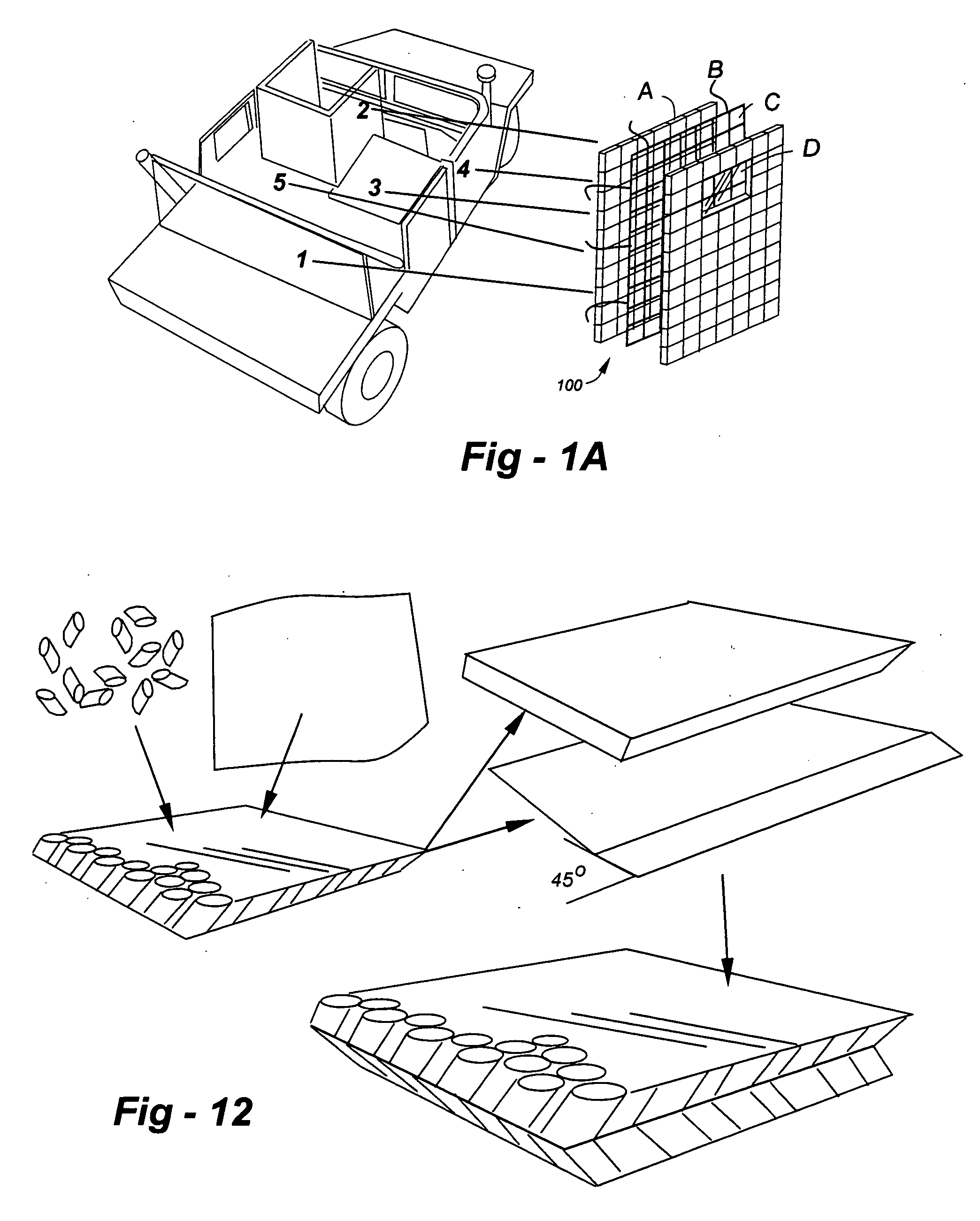
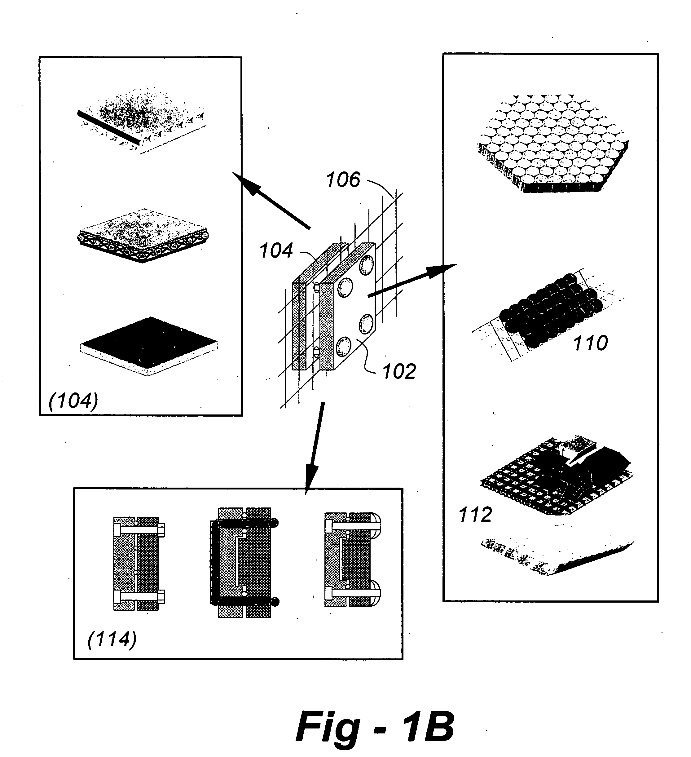
[0034] Basic armor configuration 100 according to the invention is illustrated in FIG. 1A. FIG. 1B shows different construction alternatives. Each include three major modules: 1) a functionally oriented material (FCM) tile 102 as the front plate, 2) a Bio-mimetic Tendon-Reinforced BTR back plate 104, and 3) supporting structure 106 using a fabric web. Various alternative embodiments are available in each case. As described in further detail below, the front plate may use pellets arranged in a regular structure (110), of the pellets may use a designed shape (112). The back plate may be constructed using any of the forms disclosed in co-pending U.S. patent application Ser. No. 11 / 023,923, the entire content of which is incorporated herein by reference. The front and back plates may be joined with a clip mechanism (114), or other disclosed alternatives may be used. In the preferred embodiment, the front and back plates are co-extensive, and arranged in an array shown at 100 facilitatin...


PUM


Abstract

Improved composite armor designs use optimally shaped ceramic pellets and a web system for patterning the pellets, improving manufacturability, and providing additional structural reinforcement. The result is lightweight, composite hybrid structures for ballistic protection particularly suited to tactical ground vehicles. The preferred embodiment is a combination of three major components: 1) an optimally designed web system that allows armor tiles to be attached to it and that can be easily integrated with existing vehicle structures; 2) an advanced composite armor unit using a patent-pending BTR (Bio-mimetic Tendon-Reinforced) material as the supporting structure; and 3) optimally placed “waiting materials” which can provide enhanced ballistic impact resistance, energy absorption capability and structural integrity. These “waiting materials” are structural members that are not active at the beginning of the ballistic impact, but become active when needed or the active members have failed.

Description

FIELD OF THE INVENTION [0001] This invention relates generally to ballistic armor and, in particular, to a lightweight composite ballistic armor for military and tactical vehicles. BACKGROUND OF THE INVENTION [0002] The terrorist attacks of Sep. 11, 2001 in New York City and Washington, D.C., and the current war in Iraq, have heightened the need for ballistic armor. Military vehicles, in particular, are vulnerable to higher-potency weapons such as rocket-launched grenades and other projectiles. Military personnel want lightweight, fast and maneuverable vehicles, but they also want vehicle occupants to be fully protected. Ballistic steel armor plates, while relatively inexpensive, add thousands of pounds to a vehicle, many of which were not designed to carry such loads. This has resulted in numerous engine and transmission failures as well as problems with vehicle suspensions and brakes. The additional weight reduces fuel efficiency and makes it impossible to carry additional personn...

Claims


Application Information

Patent Timeline
IPC IPC(8): F41H5/02
CPCF41H5/0492
Inventor MA, ZHENG-DONG
Owner MKP STRUCTURAL DESIGN ASSOCS
Learn More