
Implantable aneurysm closure systems and methods

a technology of aneurysm and aneurysm, applied in the field of devices, can solve the problems of inconvenient and accurate placement of mixtures, difficult or impossible retrieval of materials, interference with blood flow or nearby physiological structures, etc., and achieve the effect of reliable attachmen

Active Publication Date: 2007-04-19
PULSAR VASCULAR
View PDF101 Cites 212 Cited by
  • Summary
  • Abstract
  • Description
  • Claims
  • Application Information

AI Technical Summary

Benefits of technology

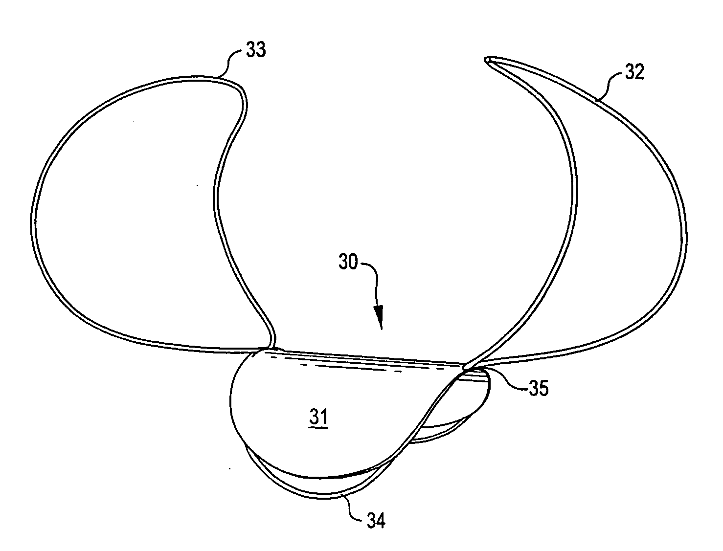
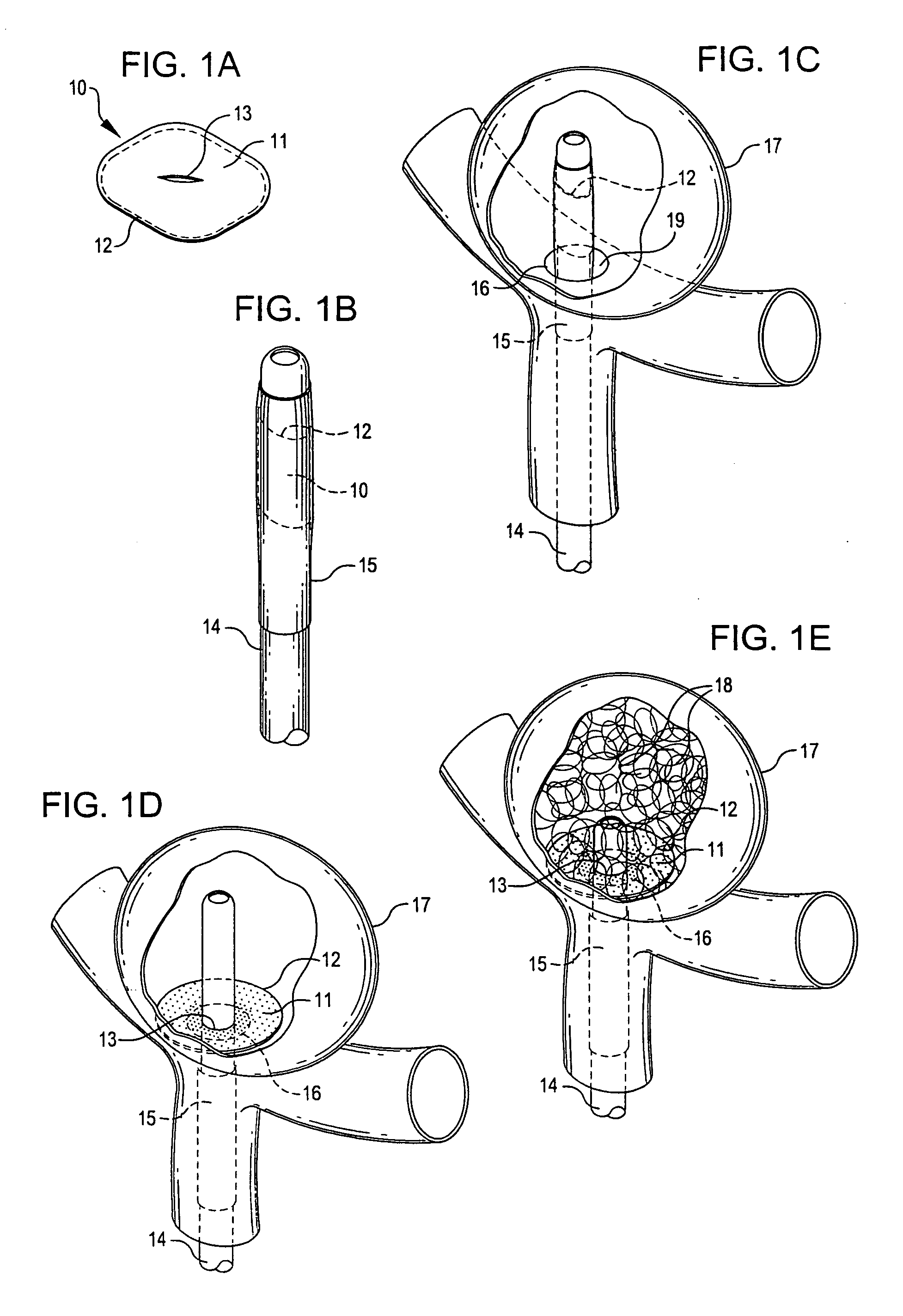
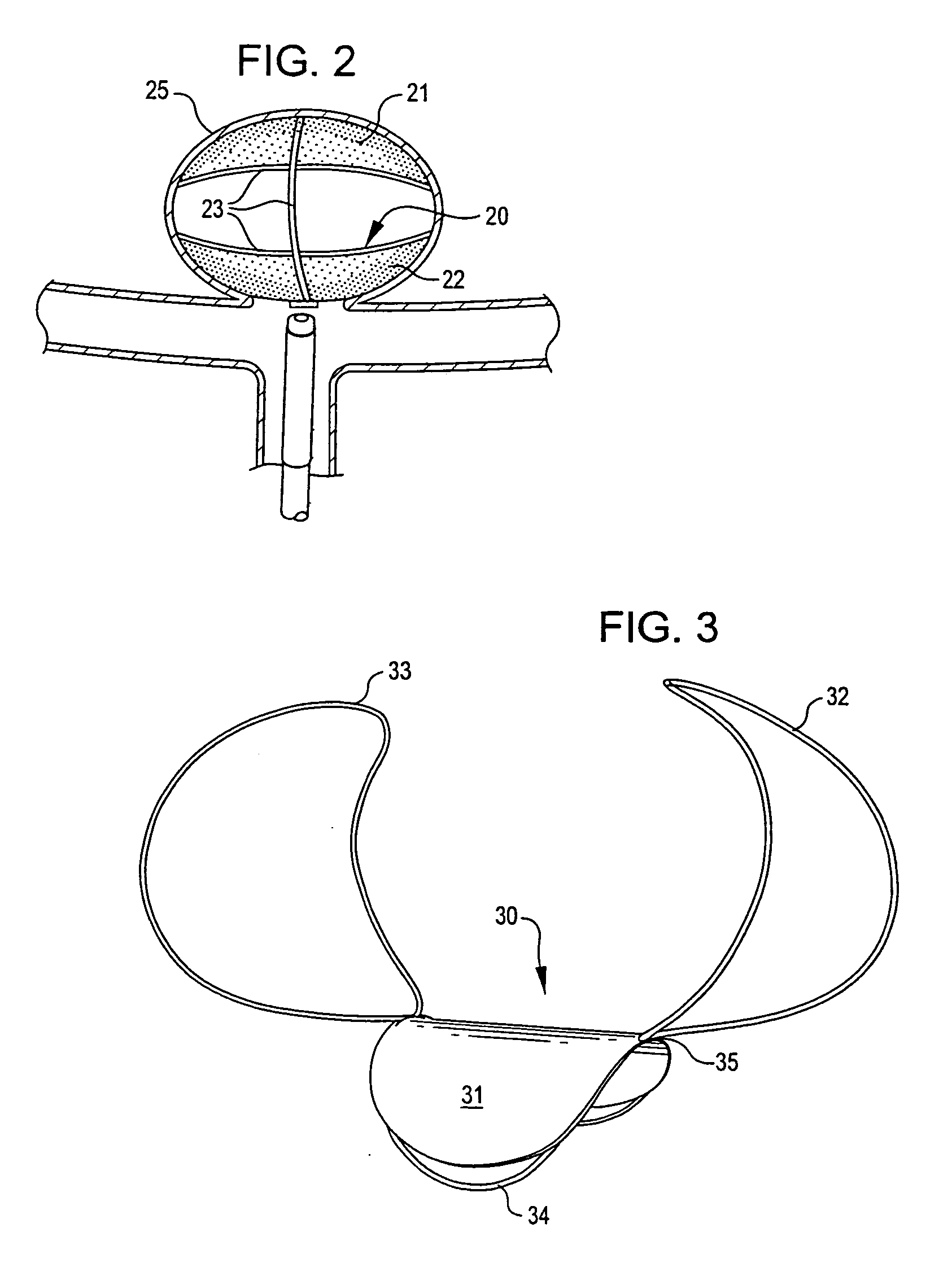
[0025] In one embodiment, the implantable device of the present invention comprises a closure structure having a flexible patch supported in the proximity of its perimeter by a wire loop or framework structure. The closure structure is adjustable between a delivery condition in which it can be delivered in a smaller dimension configuration through a catheter system to a target site and a larger dimension, deployed configuration. The size and configuration of the flexible patch in the deployed condition is preferably larger in at least one dimension than the neck or opening of the aneurysm so that the closure structure substantially covers the neck of the aneurysm when deployed. The flexible patch may provide a substantially continuous surface or, in alternative embodiments, may have one or more openings to facilitate placement using a catheter system and / or to facilitate delivery of supplemental implantable devices or agents to the interior of the aneurysm following placement of the closure structure.
[0030] The flexible patche(es) comprising closure structures of the present invention are generally constructed from a flexible material or membrane mounted to a support structure that can be delivered through a catheter and, in a deployed condition, assumes a larger dimension configuration. In one embodiment, the flexible patch is constructed from a material that is substantially impermeable to liquids such as blood and bodily fluids. Alternatively, the flexible patch may be constructed from a material that is semi-permeable to liquids such as blood and bodily fluids and allows some exchange across the membrane. The membrane may comprise, for example, a medical grade silicone material, a fabric material such as Dacron, a fluropolymer composition such as a polytetrafluoroethylene (PTFE) material such as Goretex or Teflon, or the like, that is biocompatible and biostable and compressible, foldable or otherwise deformable for assuming a low diametric profile in a delivery condition for loading into or mounting to a delivery catheter. The membrane may comprise multiple layers, and it may have a variety of coatings or other materials associated with it, such as adherent or bonding substances, therapeutic substances, radioopaque markers, and the like. The membrane may have a substantially continuous surface area or it may be provided with one or more openings or slots facilitating placement of the implantable device or mounting of the device on a catheter or delivery system in a delivery condition. The membrane is secured to a metallic loop or framework structure preferably comprising a shape change material by forming, bonding, suturing, or the like.
[0034] In this embodiment, the closure structure placed across the neck of the aneurysm may have a central opening or slot mounted on the delivery catheter for delivery in the low profile condition and through which the delivery catheter may be withdrawn. According to methods of the present invention using this system, additional embolic devices such as coils, liquid or particulate embolics, or the like, may be introduced through a delivery catheter inserted through an opening of the closure structure. The additional embolic devices may act to bias the perimeter of the closure device against the interior wall of the aneurysm and thereby assist in retaining the closure structure in position substantially covering the neck of the aneurysm.
[0036] In one deployment system, a device wire is mounted on or associated with an implantable device of the present invention. A proximal end of the device wire is mountable or mounted in proximity to a detachment mechanism comprising a shape change activation element having a generally linear configuration and being fixedly connected at its proximal end to a delivery wire, conduit, catheter or the like. The proximal end of the device wire and the distal end of the activation element have mating attachment mechanisms that, in a delivery condition, provide reliable attachment and guidance of the implantable device to the desired detachment site. Detachment of the activation element from the device wire following placement of the device at a desired location is accomplished by applying a shape change force, such as heat or current, to the activation element, producing a shape change in the activation element that releases the device wire, allowing withdrawal of the activation element and delivery wire.

Problems solved by technology

Accurate and timely placement of these mixtures is crucial and very difficult.
These materials are also difficult or impossible to retrieve once they have been placed in the vasculature.
Migration or projection of a vaso-occlusive device from the cavity may interfere with blood flow or nearby physiological structures and poses a serious health risk.
One type of aneurysm, commonly known as a “wide neck aneurysm” is known to present particular difficulty in the placement and retention of vaso-occlusive coils.
The placement of coils or other structures or materials in the internal space of an aneurysm or other defect hasn't been entirely successful.
The placement procedure may be arduous and lengthy, requiring the placement of multiple coils serially in the internal space of the aneurysm.
Debris and occlusive material may escape from within the aneurysm and present a risk of stroke, vessel blockage or other undesirable complications.
Blood flows into aneurysm and other blood vessel irregularities after the placement of embolic devices, which increases the risks of complication.
Furthermore, some aneurysms, vessels and other passageway defects aren't well-suited to placement of coils or other conventional occlusive devices.
Wide neck aneurysms continue to present challenges in the placement and retention of vaso-occlusive coils.
Such systems have the disadvantage that dissolved material or gases generated by electrolysis may be released into the vasculature, thus presenting a potential hazard to the patient.
Electrolytic detachment may also take more time to accomplish than is desirable during an interventional operation in which several occlusive devices are placed.

Method used


Image

  • Implantable aneurysm closure systems and methods
  • Implantable aneurysm closure systems and methods
  • Implantable aneurysm closure systems and methods

Examples


Embodiment Construction

[0045] Implantable devices and methods of the present invention are described and illustrated, in detail, with respect to their application as aneurysm closure devices. It will be appreciated that these devices and methods are not limited to this application and may be adapted and utilized in connection with the treatment of other vessel or air passageway cavities, abnormalities, or the like.

[0046]FIG. 1A-1E illustrate an implantable device of the present invention. FIG. 1A shows a closure structure 10 comprising a flexible patch 11 mounted or retained on a framework structure 12 and optionally having an opening or slot 13 provided in a generally central portion of patch 11. In one embodiment, patch 11 comprises a biocompatible and biostable material that is substantially impermeable to solids and liquids, such as a medical grade silicone material, a fluoropolymer material such as a PTFE composition such as Gore-Tex or Teflon, a woven or non-woven fabric material such as Dacron, or...


PUM


Abstract

An implantable closure structure is delivered using minimally invasive techniques and inhibits the migration of liquid and particulate matter from inside a physiological cavity or opening, such as an aneurysm, as well as inhibiting the flow of liquid and particulate matter, such as from an associated blood vessel, into a physiological cavity or opening. The device has a flexible patch supported by a framework structure that covers the neck or opening of a cavity such as an aneurysm and may have anchoring structures for supporting the flexible patch in place across the opening.

Description

CROSS-REFERENCE TO RELATED APPLICATIONS [0001] This application claims priority under 35 U.S.C. § 119(e) to U.S. Provisional Patent Application No. 60 / 728,052 filed Oct. 19, 2005.TECHNICAL FIELD OF THE INVENTION [0002] The present invention relates generally to devices used in connection with minimally invasive treatments, such as treatments of defects in blood vessels or gas passageways of a mammal. More specifically, the invention relates to devices and systems for occluding aneurysms, other blood vessel irregularities and other passageway irregularities using minimally invasive techniques. BACKGROUND OF THE INVENTION [0003] Occlusive devices are placed within an opening or cavity in the body, such as in the vasculature, spinal column, fallopian tubes, bile ducts, bronchial and other air passageways and the like, and are generally delivered using minimally invasive surgical techniques. In general, an implantable device is guided to a desired site through a delivery catheter and ma...

Claims


Application Information

Patent Timeline
IPC IPC(8): A61B17/08
CPCA61B17/12022A61B17/12113A61B17/12172A61B19/54A61B2017/00867A61B2017/1205A61B2017/12054A61B90/39
Inventor ESKRIDGE, JOSEPHCLARKE, GILBERT
Owner PULSAR VASCULAR
Learn More