
CD card

a technology of compact discs and cards, applied in the field of compact discs, can solve the problems of not being readily acceptable for collectors, business cards, and large cd-roms, and achieve the effects of not being able to fit in standard baseball card holders, drawers, or shelving, and not being able to accept discartTM devices

Inactive Publication Date: 2007-04-19
SERIOUS IP
View PDF20 Cites 4 Cited by
  • Summary
  • Abstract
  • Description
  • Claims
  • Application Information

AI Technical Summary

Benefits of technology

Enables digital information storage and playback in a compact, aerodynamic form factor, compatible with standard CD drives, reducing storage and handling issues while maintaining compatibility with existing CD technology.

Problems solved by technology

However, a standard 12 cm CD-ROM is rather large and awkward compared to a standard baseball card, business card, or credit card size format.
Thus, products such as the DISCART™ device may not be as readily acceptable for collectors.
Such an apparatus, for example, would not fit within standard baseball card holders, drawers, or shelving.
In addition, while the device appears to play satisfactorily in most CD players and CD-ROM drives, after testing the inventor has discovered that the device may create some vibrations or noise when played or used in some CD players or CD-ROM drives.
The rectangular shape of the disc creates a slight imbalance or non-aerodynamic shape which may result in vibration in some CD players.
The presence of protruding knobs may make the card less useful as a business card device, as the resultant card is no longer flat.
As such, storage devices for business cards, baseball cards, and the like, may not readily accept such a card.
The knobs also make the card less aerodynamic and cause greater vibration.
However, even an 8 cm CD is too large to fit in a standard baseball or business card size format.
90 to 95% of CD players used today are tray loading drive types with 8 cm aligning circles, making these adapters unnecessary in the majority of CD players.
Although the device of Yamamori may be suitable for playing back 8 cm discs, the overall structure of the apparatus suffers from some drawbacks.
It also requires excess handling of the 8 cm disc and the possibility of disengagement of the adaptor from the disc resulting in damage to the disc or the disc drive.
However, all of those devices appear to suffer from the same fundamental limitations of the Yamamori device.
In particular, the overall size of such adapters precludes them from being packaged into a package substantially smaller than a standard 12 cm CD-ROM.
Such a device may not be readily adaptable to a tray-type CD-ROM player or the like.
Without such a depression, the 8 cm CD-ROM may slide about when the tray is closed, and the spindle may not properly engage, possibly damaging or scratching the 8 cm CD-ROM.
While such a solution may work for an 8 cm CD-ROM, it may not work for other, odd sizes.
Given the large installed base of CD-ROM drives, one wishing to distribute a non-standard (e.g., diameter other than 8 cm or 12 cm) CD-ROM size, one cannot expect users to buy new CD-ROM drives with yet a second depression for yet another size CD-ROM.

Method used


Image

  • CD card
  • CD card
  • CD card

Examples


first embodiment

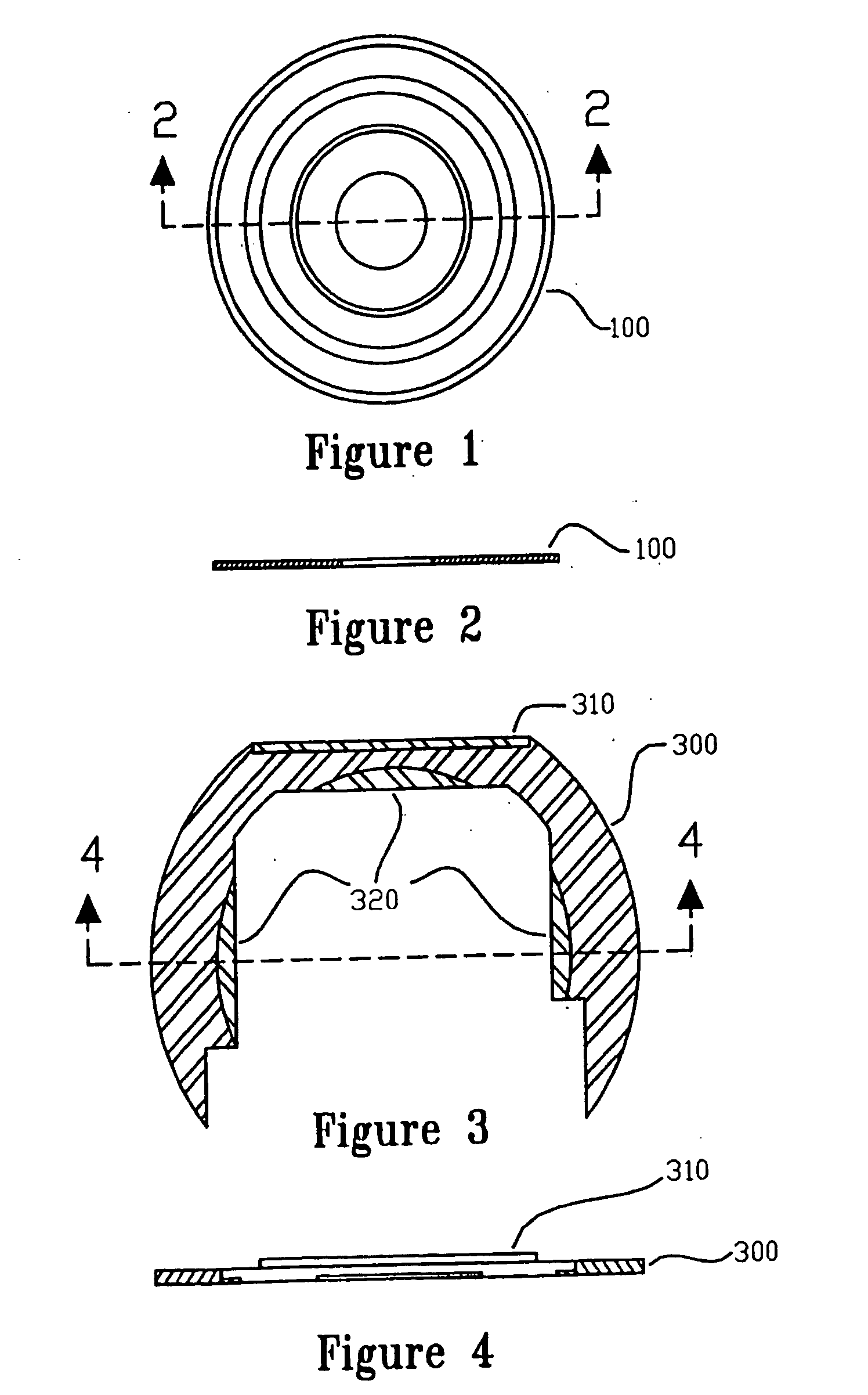
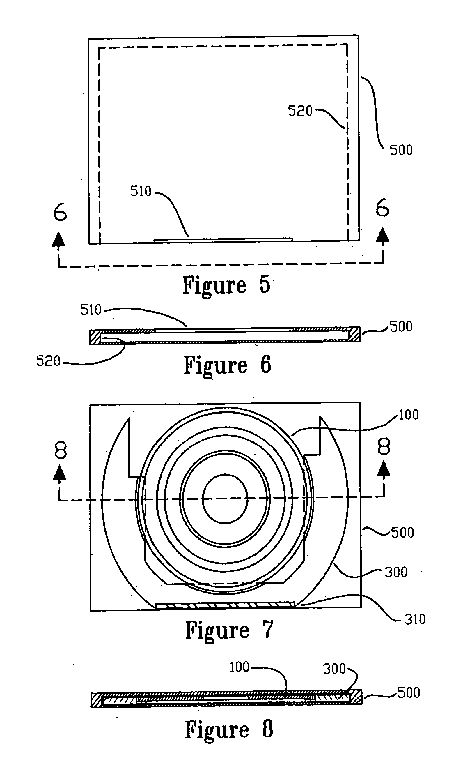
[0051]FIG. 1 is a top plan view of the small compact disc of the present invention. Disc 100 uses the same technologies, materials, and data standards as does the standard 12 or 8 cm CD, with the only significant exception being that its outside diameter is substantially smaller than a typical prior art 8 or 12 cm compact disc. In the preferred embodiment, the disc is approximately 5.5 to 6.35 cm in diameter.

[0052]FIG. 2 is a cross-section taken along lines 2-2 of FIG. 1, illustrating a cross-sectional view of disc 100.

[0053]FIG. 3 is a top plan view of an adaptor of the first embodiment of the present invention. Adaptor 300 may be substantially “C”-shaped having an outer diameter of approximately 8 cm. Adaptor 300 may be provided with lands 320 which may be adapted to received the disc 100 when it is placed upon lands 320. Adaptor 300 may also be provided with a ridge 310, the function of which will be described below.

[0054] Note that adaptor 300, although adapted to approximatel...

second embodiment

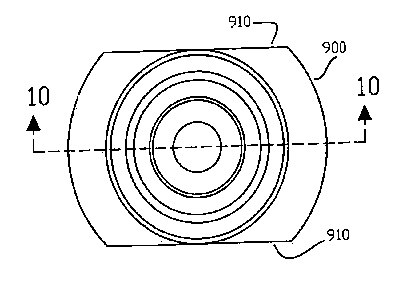
[0061]FIG. 9 is a top plan view of the present invention of a small compact disc 900. Disc 900 may be provided with a nominal diameter of approximately 8 cm, but having substantially parallel portions 910. The distance between substantially parallel portions 910 may be approximately 5.5 to 6.35 cm. Data may be written into that portion of the disc having a diameter less than the distance between substantially parallel portions 910. Although disc 900 is not round (as with disc 100), unlike prior art rectangular discs, disc 900 is smaller with a greater percentage of the edge of the disc being circular and thus making it more aerodynamic, easier to balance, and simpler to align in the depressed portion (8 cm diameter circle) of the compact disc reader tray. Disc 900 may optionally be provided with balancing weights (not shown) in the form of denser or thicker portions which may serve to dynamically balance disc 900.

[0062]FIG. 10 is a cross-section taken along lines 10-10 of FIG. 9.

[0...

third embodiment

[0066]FIG. 15 is a top plan view of the present invention of the small compact disc. Disc 1500 is similar for all intents and purposes as disc 100 of FIG. 1.

[0067]FIG. 16 is a cross-section taken along lines 2-2 of FIG. 15.

[0068]FIG. 17 is a top plan view of the third embodiment of the present invention illustrating an adaptor. The adaptor of FIG. 17 differs slightly from that of FIG. 3 in that the overall adaptor does not have rounded edges. Rather, raised edges 1710 are provided at a diameter approximately 8 cm across the center of adaptor 1700. Raised edges 1710 may rest inside a depressed portion of a CD-ROM drive designed to accommodate 8 cm discs. Disc 1500 may be carried on adaptor 1700 on lands, such as lands 320 shown in FIG. 3. In the alternative, adaptor 1700 may merely center disc 1500 and thus not actually carry or be in contact with disc 1500.

[0069]FIG. 18 is a cross-section taken along lines 4-4 of FIG. 17, illustrating the shape of raised edges 1710.

[0070]FIG. 19 ...


PUM

PropertyMeasurementUnit
diameteraaaaaaaaaa
diameteraaaaaaaaaa
diameteraaaaaaaaaa

Abstract

A CD Card for packaging card like information and digital information in the basic dimensions (length and width) of a business, credit or collectors card. The CD Card is made up of one, two, or three major components. The first component is a small compact disc with dimensions small enough to be contained within the typical dimensions (length and width) of a business card, credit card, or collectors card. The second component is a container shaped like a business, credit, or collectors card in length and width, but with a depth large enough to hold the small compact disc and adaptor (if required) discussed subsequently. The third component is an adaptor designed to position the small compact disc of the first and third embodiments of the present invention correctly in standard CD drives. A second embodiment of the small compact disc may not require an adaptor or case. The adaptor also has dimensions small enough to be contained within the typical dimensions (length and width) of a business card, credit card, or collectors card.

Description

CROSS-REFERENCE TO RELATED APPLICATIONS [0001] The present application is a Continuation of U.S. patent application Ser. No. 10 / 106,857 filed on Mar. 27, 2002, and incorporated herein by reference, which in turn is a Continuation of U.S. patent application Ser. No. 09 / 170,040, filed on Oct. 13, 1998, and incorporated herein by reference, which in turn claims priority from Provisional U.S. application Ser. No. 60 / 062,408, filed Oct. 14, 1997, which is incorporated herein by reference.FIELD OF THE INVENTION [0002] The present invention relates to the field of compact disc (CD) data storage, specifically to a method and apparatus for packaging a smaller size compact disc, or a smaller size compact disc and disc adaptor into a credit card, business card, or baseball card / collectors card size. BACKGROUND OF THE INVENTION [0003] It may be desirable to be able to distribute digital information in a medium as widely accepted and easily carried as a business, credit, or collectors card that ...

Claims


Application Information

Patent Timeline
Patent Type & Authority Applications(United States)
IPC IPC(8): G11B11/00G11B7/0033G11B7/24G11B23/00G11B23/03
CPCG11B7/0033G11B7/24G11B23/0021G11B23/0316G11B23/0327
Inventor WOOD, DAVID B.
Owner SERIOUS IP
Learn More