
Device for supporting and housing auxiliaries in a bypass turbojet

a technology of auxiliaries and bypass turbojets, which is applied in the direction of stators, machines/engines, transportation and packaging, etc., can solve the problem that the internal case ring cannot be aligned with the radial arms, and the technique cannot be used to gain access to equipment situated inside the internal case ring. , to achieve the effect of simple, effective and economi

Active Publication Date: 2007-04-19
SN DETUDE & DE CONSTR DE MOTEURS DAVIATION S N E C M A
View PDF13 Cites 35 Cited by
  • Summary
  • Abstract
  • Description
  • Claims
  • Application Information

AI Technical Summary

Benefits of technology

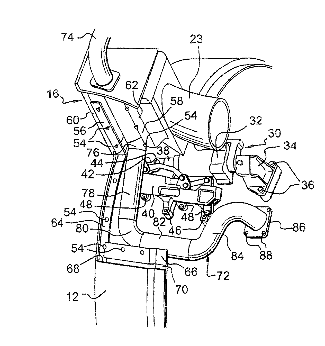
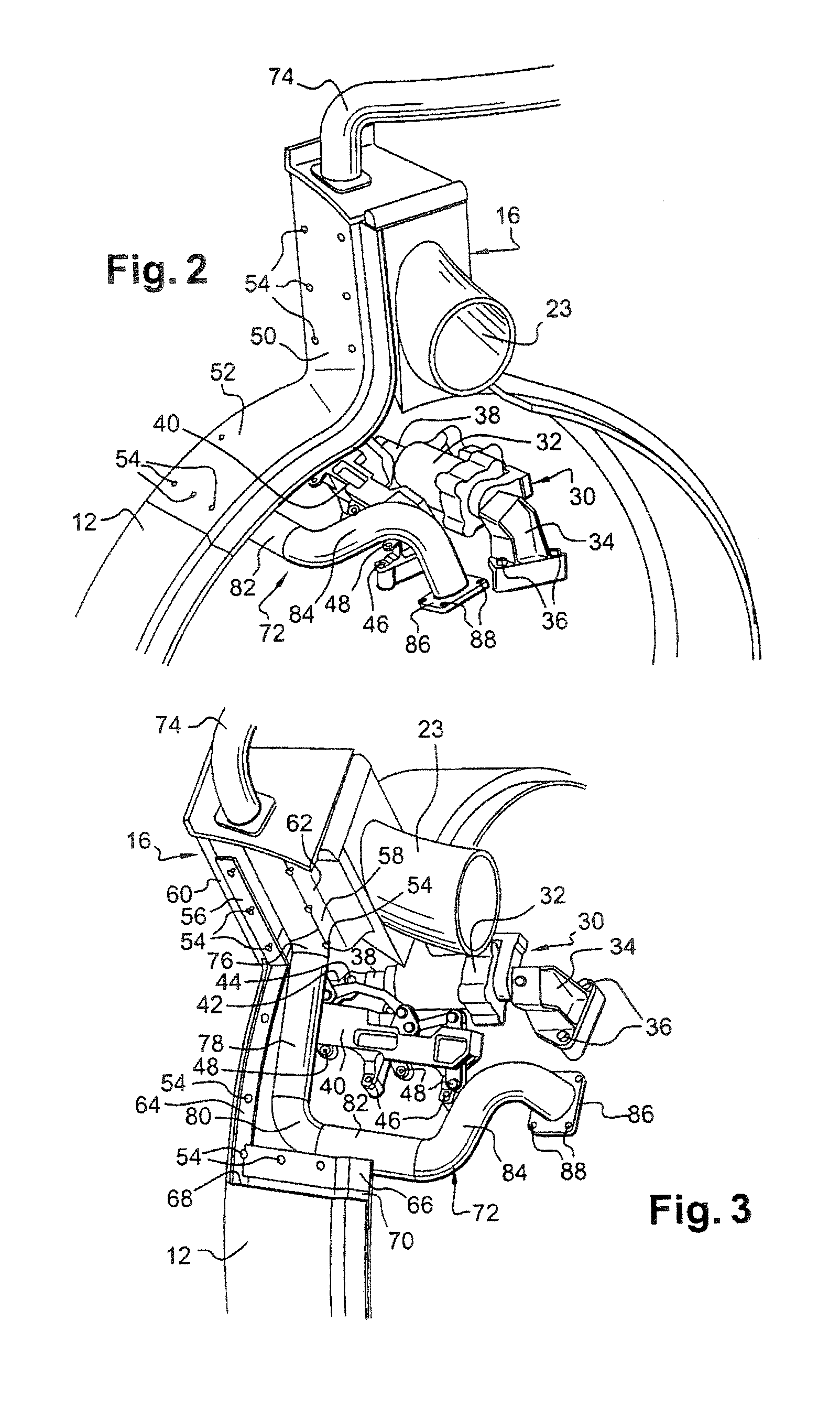
[0008] In the device according to the invention, the radial arms situated above the turbojet equipment subject to maintenance operations each comprise on one of their lateral faces a detachable panel which is fastened by screws or the like to the radial arm. Maintenance operations on equipment situated in alignment with the radial arms are thus easier to carry out and can be performed directly on a turbojet mounted under the wing of an aircraft.
[0009] The removal of the detachable panels from the radial arms also makes it possible to have access to the electric cables or to the fluid ducts which pass through these radial arms. These ducts and cables can thus be disassembled and replaced easily.
[0010] According to another feature of the invention, the detachable panel comprises a radial portion fastened to the radial arm and a cylindrical portion for connection to the internal case ring. This improves access to and the visibility of the turbojet equipment situated inside the internal case ring, facilitates the use of tools for the disassembly and maintenance of said equipment, and allows the withdrawal of certain equipment for replacement thereof.
[0015] These sealing gaskets have good heat resistance and make it possible to limit or even prevent a fire occurring inside the engine from propagating radially outwardly into the bypass stream.

Problems solved by technology

However, this technique does not make it possible to gain access to equipment situated inside the internal case ring in alignment with the radial arms, for example of the Line Replaceable Unit (LRU) type such as actuators for controlling the angular setting of the compressor stators, which have to be able to be disassembled without disassembly of the case rings of the device for supporting auxiliaries.

Method used


Image

  • Device for supporting and housing auxiliaries in a bypass turbojet
  • Device for supporting and housing auxiliaries in a bypass turbojet
  • Device for supporting and housing auxiliaries in a bypass turbojet

Examples


Embodiment Construction

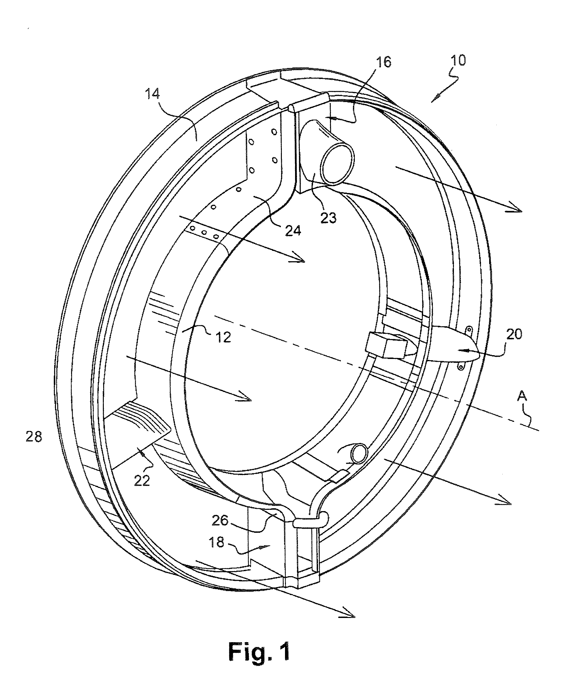
[0025]FIG. 1 represents a device 10 according to the invention for supporting and housing auxiliaries in a bypass turbojet, this device comprising two coaxial cylindrical case rings 12, 14 which extend one around the other and which are interconnected by radial arms 16, 18, 20 and 22, some of these arms 16, 18 having a detachable lateral panel 24, 26 allowing access to turbojet equipment situated inside the internal case ring, and at least partly in alignment with the radial arm, for a maintenance operation.

[0026] This device is mounted downstream of the turbojet fan and the internal case ring 12 surrounds an external casing of the turbojet compressor, at a distance from this casing, and extends axially in alignment with another casing of the turbojet. The internal case ring 12 defines, with the external case ring 14, an annular flow path for the bypass stream originating from the fan, which is schematically represented by arrows.

[0027] At its upstream and downstream ends, the ext...


PUM


Abstract

A device for supporting and housing auxiliaries in a bypass turbojet, comprising two coaxial case rings arranged one inside the other and connected by tubular radial arms through which fluid ducts and electric cables pass, at least one of the radial arms comprising on a lateral face a detachable panel whose removal allows access to turbojet equipment situated radially inside the internal case ring in alignment with the radial arm.

Description

BACKGROUND OF THE INVENTION [0001] The present invention relates to a device for supporting and housing auxiliaries in a bypass turbojet, this device comprising two coaxial case rings arranged one inside the other and connected by tubular radial arms through which fluid ducts and electric cables pass. [0002] This device is mounted around a compressor of the turbojet, downstream of the fan and upstream of a turbine of the turbojet, and can cooperate via its external case ring with a thrust reverser mounted downstream of this device. [0003] The internal and external case rings of the device define between them an annular flow path for the bypass stream which originates from the fan of the turbojet and which is intended in particular for cooling components of the turbojet. DESCRIPTION OF THE PRIOR ART [0004] In the known art, the radial arms of this device are in one piece and the internal case ring comprises panels in the form of cylinder portions (extending for example over 90°) whic...

Claims


Application Information

Patent Timeline
Patent Type & Authority Applications(United States)
IPC IPC(8): F02C7/32
CPCF01D9/065F02K3/04
Inventor MAZEAUD, GEORGESYVON, DIDIER JEAN-LOUIS
Owner SN DETUDE & DE CONSTR DE MOTEURS DAVIATION S N E C M A
Learn More