Compression device for a laser handpiece

a laser and handpiece technology, applied in the field of compression devices for laser handpieces, can solve the problems of unfavorable patient safety, unfavorable patient safety, undesired purpura, etc., and achieve the effect of avoiding unwanted damage to tissue surrounding the target region and little or no injury to surrounding tissu

Inactive Publication Date: 2007-04-12
CANDELA CORP
View PDF99 Cites 14 Cited by
  • Summary
  • Abstract
  • Description
  • Claims
  • Application Information

AI Technical Summary

Benefits of technology

[0008] The invention, in various embodiments, features a method and apparatus for delivering a beam of radiation to a target region of skin. The beam of radiation can be used to treat cosmetically pigmented and / or vascular lesions. The apparatus can include a compression device to displace unwanted chromophores from the target region. For example, a compression device can be used to displace blood from tissue in a target region while a beam of radiation targeting melanin is delivered to treat a pigmented lesion. In another example, a compression device can be used to displace blood from superficial capillaries while a beam of radiation targeting deeper blood vessels is used to treat an underlying vessel. An appropriate wavelength and pulse duration can be chosen to selectively damage or destroy the pigmented lesion with little or no injury to surrounding tissue. The compression device can include a negative focal length to diverge the beam of radiation to avoid unwanted damage to tissue surrounding the target region.
[0009] A treatment can include cooling to protect the skin surface, to minimize unwanted injury to the surface of the skin, and to minimize any pain that a patient may feel. An additional advantage of such a treatment according to the invention is that the treatment can be performed with minimal cosmetic disturbance such that the patient can return to normal activity immediately after the treatment.
[0010] Furthermore, the compression device can be used to treat blood vessels (e.g., varicose veins, telangiectasias, and reticular veins). The compression device can compress a targeted vessel. Compressing the vessel can reduce the diameter and / or change the shape of the targeted vessel so that radiation more uniformly irradiates the vessel. This can result in a more uniform heat distribution within the vessel and the vessel wall, and increase the efficiency of a treatment.
[0016] In yet another aspect, the invention features an apparatus for contact cooling a target region of skin. The apparatus includes a housing, a transmitter of optical radiation into said housing, and a meniscus lens disposed on the housing in pressure contact with a surface of the target region of skin. The apparatus also includes an optical element and a cooling medium. The optical element is disposed on the housing and positioned between the transmitter and the meniscus lens, and the cooling medium passes through the housing and across a surface of the meniscus lens to cool the surface of the target region of skin below the temperature of the target region of skin.
[0020] In some embodiments, an optical element can be used to substantially uniformly displace blood from a portion of the target region of skin (e.g., to minimize an unwanted side effect of a treatment). The blood displaced can be blood underlying a pigmented lesion, or overlying a vascular lesion. In various embodiments, a distance gauge can be disposed relative to the first end of the housing to position the housing spaced from the target region of skin. The distance gauge can define a hole for retaining the optical element and / or the meniscus lens.

Problems solved by technology

Components of blood (e.g., hemoglobin, oxyhemoglobin, and methemoglobin) strongly absorb between 400 nm and 1,100 nm; therefore, extraneous light from a beam of radiation targeting a pigmented lesion in this wavelength region can be absorbed by one or more of these components of blood, resulting in unwanted side effects, such as purpura.
Furthermore, undesired purpura can also result during treatment of vascular lesions, such as leg veins or facial telangiectasias.
A disadvantage of a flat lens, though, is that it does not uniformly displace blood.
The planoconvex lens can be adapted to focus the beam of radiation below the surface of the skin, but if contact is not maintained between the skin and the lens while the beam of radiation is being delivered, the focal point of the radiation can change resulting in unwanted damage to the skin.
For example, if the lens is withdrawn from the surface of the skin, the focal point of the lens can fall on the surface of the tissue causing a burn or resulting in a scar.

Method used


Image

  • Compression device for a laser handpiece
  • Compression device for a laser handpiece
  • Compression device for a laser handpiece

Examples


Embodiment Construction

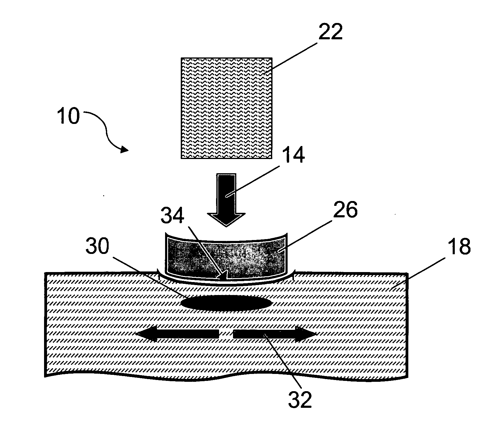
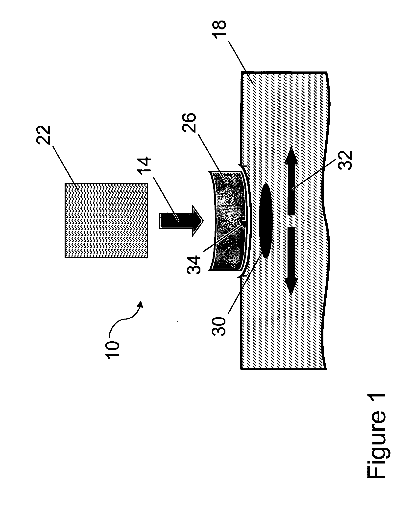
[0032]FIG. 1 shows an illustrative embodiment of an apparatus 10 delivering a beam of radiation 14 to a target region of skin 18. The apparatus includes a source 22 of the beam of radiation 14 and an optical element 26 for compressing the skin. The source 22 can generate the beam of radiation 14, or the source 22 can be a transmitter that delivers the beam of radiation to the target region of skin 18. For example, the transmitter can be an optical fiber or an optical waveguide. In other embodiments, the transmitter can include an articulated arm or an optical system that delivers a beam of radiation produced by a source through a system of lenses. Suitable optical elements 26 can include, but are not limited to, a lens and a plurality of lens. In the embodiment illustrated in FIG. 1, the optical element is a meniscus lens.

[0033] The target region of skin 18 can include a target feature 30, such as a pigmented lesion and / or a vascular lesion. In some embodiments, the beam of radiati...


PUM


Abstract

A cosmetic condition (e.g., a pigmented lesion or a vascular lesion) can be treated using a delivery system that displaces blood from a target region of skin. The delivery system can include an optical element having a convex surface. The optical element can be a non-converging optical element that transmits the beam of radiation to the target region of skin.

Description

CROSS-REFERENCE TO RELATED APPLICATION [0001] This application claims priority to and the benefit of U.S. provisional patent application Ser. No. 60 / 725,920 filed Oct. 11, 2005, the entire disclosure of which is herein incorporated by reference.FIELD OF THE INVENTION [0002] The invention relates generally to using a beam of radiation and a compression device to treat a cosmetic condition, lesion, or disorder. BACKGROUND OF THE INVENTION [0003] Pigmented lesions contain a light-absorbing chromophore, melanin, that has a broad absorption spectrum. Absorbance of light by melanin is strongest in the ultraviolet (UV) region of the electromagnetic spectrum and gradually diminishes toward the infrared region. Components of blood (e.g., hemoglobin, oxyhemoglobin, and methemoglobin) strongly absorb between 400 nm and 1,100 nm; therefore, extraneous light from a beam of radiation targeting a pigmented lesion in this wavelength region can be absorbed by one or more of these components of blood...

Claims


Application Information

Patent Timeline
Patent Type & Authority Applications(United States)
IPC IPC(8): A61B18/18
CPCA61B18/203A61B2018/00452A61B2018/0047
Inventor DOMANKEVITZ, YACOV
Owner CANDELA CORP
Why Eureka
Try Eureka