
System, method, and apparatus for enhancing the durability of earth-boring bits with carbide materials

Active Publication Date: 2007-04-12
BAKER HUGHES INC
View PDF28 Cites 31 Cited by
  • Summary
  • Abstract
  • Description
  • Claims
  • Application Information

AI Technical Summary

Benefits of technology

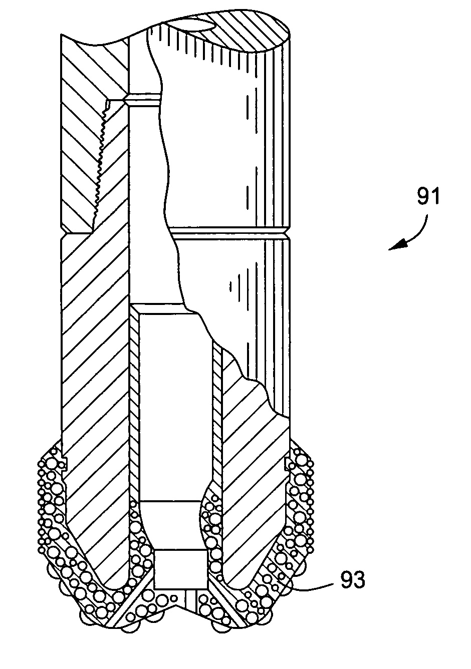
[0011] One embodiment of a system, method, and apparatus for enhancing the durability of earth-boring bits with carbide materials is disclosed. Drill bits having a drill bit body with a cutting component include a composite material formed from a binder and tungsten carbide crystals. In one embodiment, the crystals have a generally spheroidal shape, and a mean grai

Problems solved by technology

Additionally, the bit and cutting elements are subjected to substantial abrasive forces.
In some instances, impact, lateral and / or abrasive forces have caused drill bit failure and cutter loss.
While steel body bits have toughness and ductility properties which render them resistant to cracking and failure due to impact forces generated during drilling, steel is subject to rapid erosion due to abrasive forces, such as high velocity drilling fluids, during drilling.
However, tungsten carbide and other erosion resistant materials are brittle.
During use, the relatively thin hardfacing deposit may crack and peel, revealing the softer steel body which is then rapidly eroded.
This leads to cutter loss, as the area around the cutter is eroded away, and eventual failure of the bit.
Such tungsten carbide or other hard metal matrix bits, however, are brittle and can crack upon being subjected to impact forces encountered during drilling.
Additionally, thermal stresses from the heat generated during fabrication of the bit or during drilling may cause cracks to form.
Typically, such cracks occur where the cutter elements have been secured to the matrix body.
If the cutter elements are sheared from the drill bit body, the expensive diamonds on the cutter elements are lost, and the bit may cease to drill.
Additionally, tungsten carbide is very expensive in comparison with steel as a material of fabrication.

Method used


Image

  • System, method, and apparatus for enhancing the durability of earth-boring bits with carbide materials
  • System, method, and apparatus for enhancing the durability of earth-boring bits with carbide materials
  • System, method, and apparatus for enhancing the durability of earth-boring bits with carbide materials

Examples


Embodiment Construction

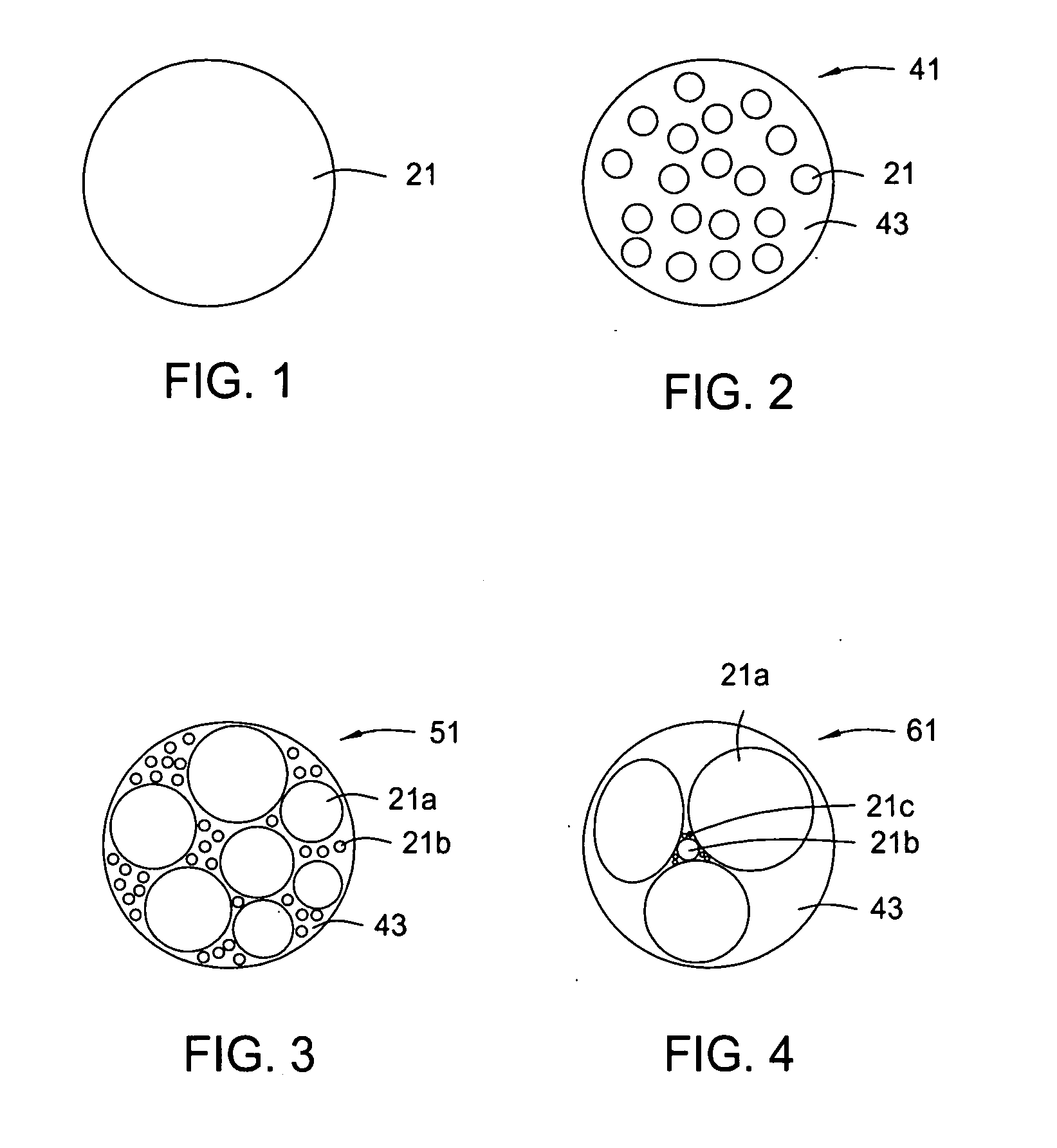
[0029] Referring to FIG. 1, one embodiment of a carbide crystal 21 constructed in accordance with the present invention is depicted in a simplified rounded form. In the embodiment shown, crystal 21 is formed from tungsten carbide (WC) and has a mean grain size range of about 0.5 to 8 microns, depending on the application. The term “mean grain size” refers to an average diameter of the particle, which may be somewhat irregularly shaped.

[0030] Referring now to FIG. 2, one embodiment of the crystals 21 are shown formed in a sintered spheroidal pellet 41. Neither crystals 21 nor pellets 41 are drawn to scale and they are illustrated in a simplified manner for reference purposes only. The invention should not be construed or limited because of these representations. For example, other possible shapes include elongated or oblong rounded structures, etc.

[0031] Pellet 41 is suitable for use in, for example, a hardfacing for drill bits. The pellet 41 is formed by a plurality of the crystal...


PUM

PropertyMeasurementUnit
Grain sizeaaaaaaaaaa
Lengthaaaaaaaaaa
Lengthaaaaaaaaaa

Abstract

An earth-boring drill bit having a bit body with a cutting component formed from a tungsten carbide composite material is disclosed. The composite material includes a binder and tungsten carbide crystals comprising sintered pellets. The composite material may be used as a hardfacing on the body and / or cutting elements, or be used to form portions or all of the body and cutting elements. The pellets may be formed with a single mode or multi-modal size distribution of the crystals.

Description

[0001] This application claims priority to U.S. Provisional Patent Application Ser. Nos. 60 / 725,447, and 60 / 725,585, both filed on Oct. 11, 2005, and are incorporated herein by reference.BACKGROUND OF THE INVENTION [0002] 1. Technical Field [0003] The present invention relates in general to earth-boring bits and, in particular, to an improved system, method, and apparatus for enhancing the durability of earth-boring bits with carbide materials. [0004] 2. Description of the Related Art [0005] Typically, earth boring drill bits include an integral bit body that may be formed from steel or fabricated of a hard matrix material such as tungsten carbide. In one type of drill bit, a plurality of diamond cutter devices are mounted along the exterior face of the bit body. Each diamond cutter typically has a stud portion which is mounted in a recess in the exterior face of the bit body. Depending upon the design of the bit body and the type of diamonds used, the cutters are either positioned ...

Claims


Application Information

Patent Timeline
IPC IPC(8): E21B10/00
CPCB22F2005/001B22F2998/00C22C29/08E21B10/46B22F1/0014B22F1/0048B22F1/065B22F1/052
Inventor CURRY, DAVID A.OVERSTREET, JAMES L.EASON, JIMMY W.
Owner BAKER HUGHES INC
Learn More