
Semiconductor device and method of fabricating the same

Inactive Publication Date: 2007-04-05
SAMSUNG ELECTRONICS CO LTD
View PDF22 Cites 17 Cited by
  • Summary
  • Abstract
  • Description
  • Claims
  • Application Information

AI Technical Summary

Benefits of technology

[0011] Example embodiments also relate a semiconductor device and a method of fabricating the same capable of improving reliability and achieving high integration.

Problems solved by technology

The shorter channel length may cause various problems (e.g., punch through, leakage current, etc.).
An increase in leakage current may undesirably decrease the data retention time of a memory cell.
In a highly-integrated transistor, it may be difficult to form a silicide layer in the source and drain regions due to a leakage current caused by a small junction depth.
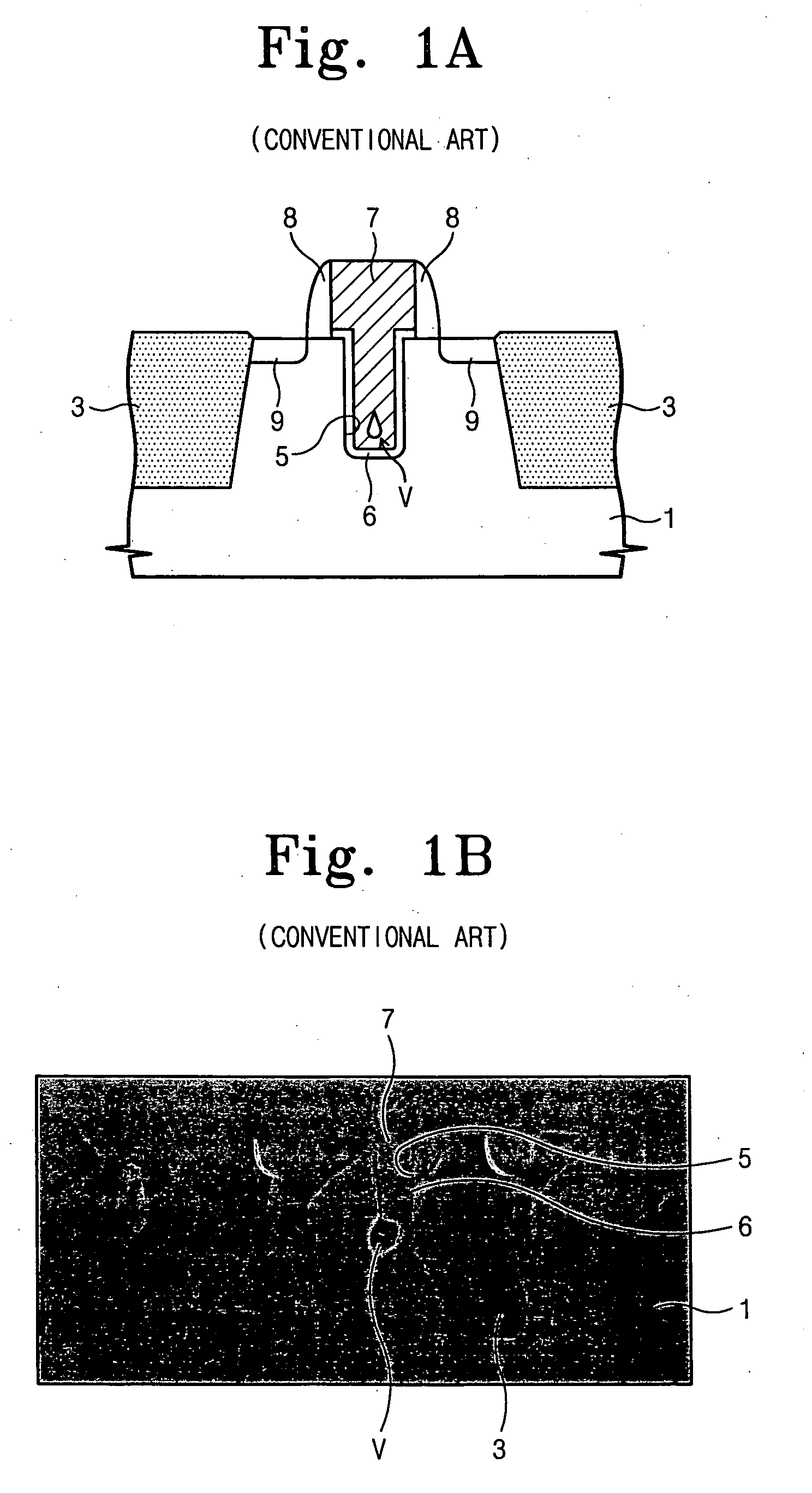
When the semiconductor device operates, the void may cause channel formation to be difficult or may cause a threshold voltage to increase, which may degrade the reliability of the semiconductor device.
As illustrated in FIG. 1B, the heat treatment process performed at the high temperature may cause severe damage to the shallow trench isolation layers 3.
When a highly-integrated semiconductor device is fabricated, misalignment with respect to the recess region 5 may occur during the photolithography process, which may have an undesirable effect upon characteristics of the transistor.

Method used


Image

  • Semiconductor device and method of fabricating the same
  • Semiconductor device and method of fabricating the same
  • Semiconductor device and method of fabricating the same

Examples


Embodiment Construction

[0035] Various example embodiments will now be described more fully with reference to the accompanying drawings in which some example embodiments are shown. In the drawings, the thicknesses of layers and regions may be exaggerated for clarity.

[0036] Detailed illustrative embodiments are disclosed herein. However, specific structural and functional details disclosed herein are merely representative for purposes of describing example embodiments. This invention may, however, may be embodied in many alternate forms and should not be construed as limited to only the example embodiments set forth herein.

[0037] Accordingly, while the example embodiments are capable of various modifications and alternative forms, embodiments thereof are shown by way of example in the drawings and will herein be described in detail. It should be understood, however, that there is no intent to limit example embodiments to the particular forms disclosed, but on the contrary, the example embodiments are to c...


PUM


Abstract

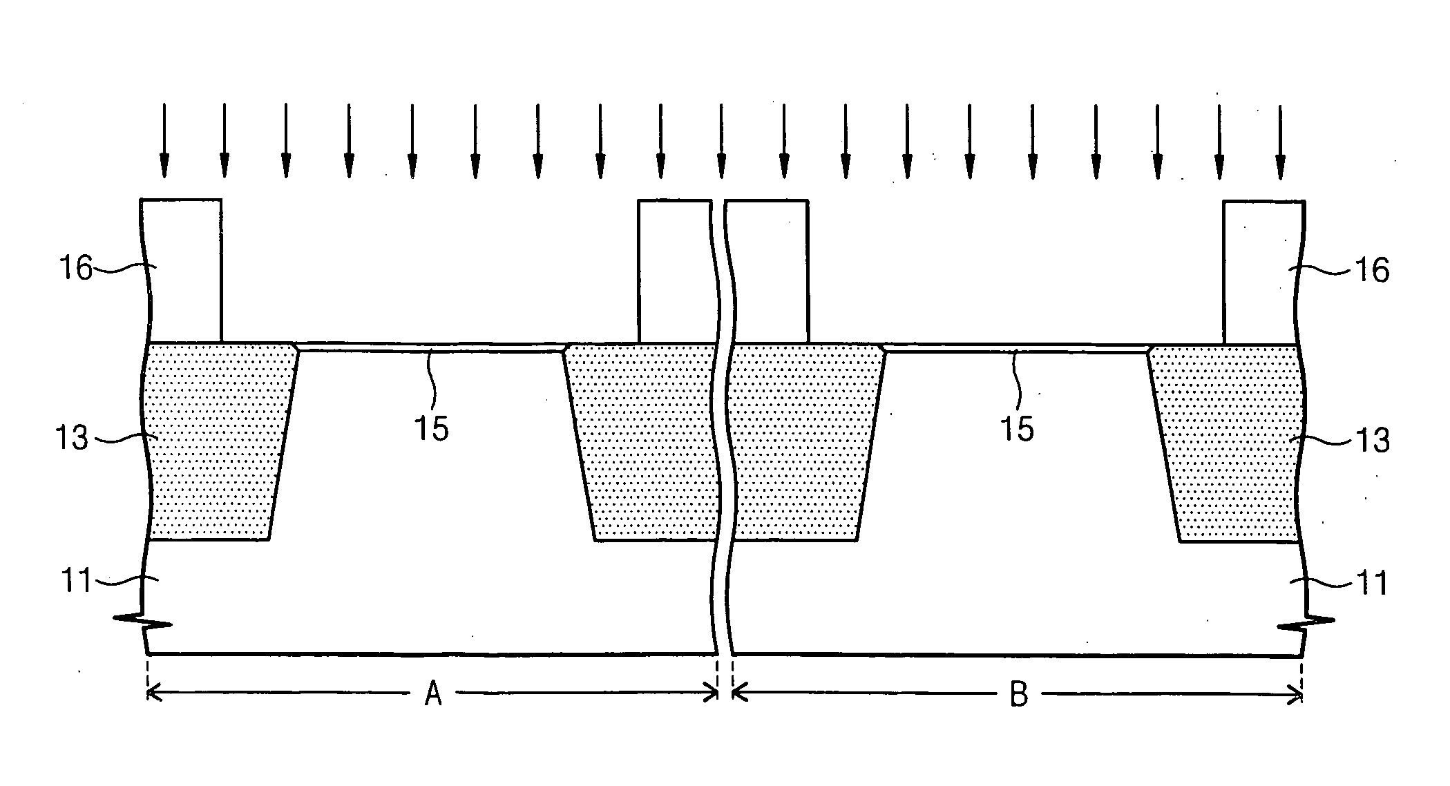
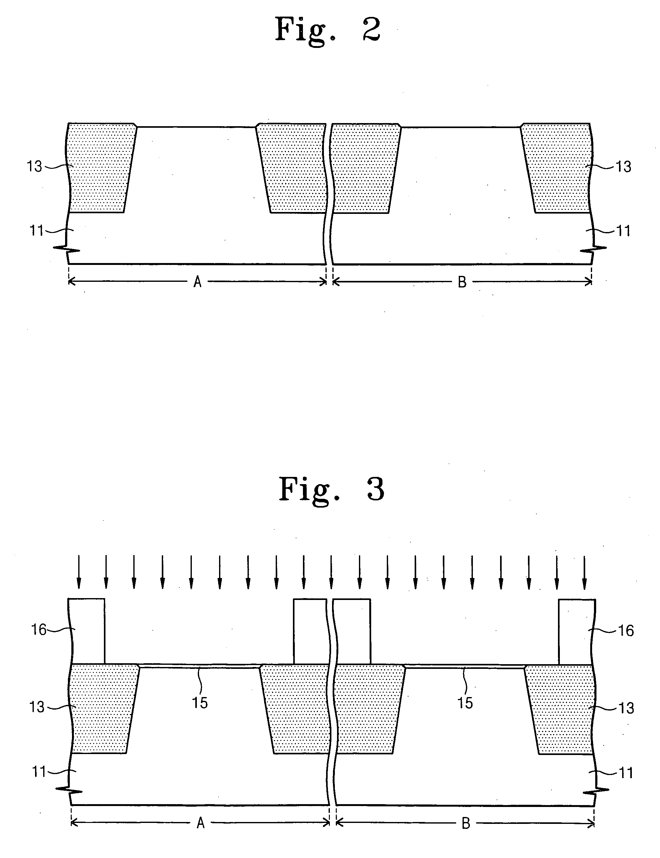
Example embodiments relate to a semiconductor device and a method of fabricating the same. A dummy pattern may be formed on a semiconductor substrate. Source and drain regions may be formed on the semiconductor substrate at sides of the dummy pattern. A first metal silicide layer may be formed on the source and drain regions. A recess region may be formed in the semiconductor substrate under the dummy pattern. A gate insulating layer and a gate electrode may be formed in the recess region.

Description

PRIORITY STATEMENT [0001] This application claims the benefit of priority under 35 U.S.C. §119 from Korean Patent Application No. 10-2005-0093002, filed on Oct. 4, 2005, in the Korean Intellectual Property Office, the disclosure of which is incorporated herein by reference in its entirety. BACKGROUND OF THE INVENTION [0002] 1. Field of the Invention [0003] Example embodiments relate to a semiconductor device and a method of fabrication the same. Other example embodiments relate to a semiconductor device having a recessed channel array transistor and a method of fabricating the same. [0004] 2. Description of the Related Art [0005] As semiconductor devices become more highly integrated, the channel length of a transistor becomes shorter. The shorter channel length may cause various problems (e.g., punch through, leakage current, etc.). An increase in leakage current may undesirably decrease the data retention time of a memory cell. In a highly-integrated transistor, it may be difficul...

Claims


Application Information

Patent Timeline
IPC IPC(8): H01L21/336
CPCH01L21/823437H01L21/82345H01L21/823456H01L21/823462H01L29/4236H01L29/66545H01L29/66553H01L29/66621H01L21/18
Inventor KANG, TAE-WOONGLEE, BYEONG-RYEOLHWANG, SUNG-MAN
Owner SAMSUNG ELECTRONICS CO LTD
Learn More