
Lighting and/or signaling device for a motor vehicle incorporating a material having thermal anisotropy

a technology of thermal anisotropy and signaling device, which is applied in the direction of lighting support device, fixed installation, lighting and heating apparatus, etc., can solve the problems of new constraints, difficult to overcome thermal management constraints, and difficulty in power led diodes in headlights and signaling lights

Inactive Publication Date: 2007-04-05
VALEO VISION SA
View PDF25 Cites 60 Cited by
  • Summary
  • Abstract
  • Description
  • Claims
  • Application Information

AI Technical Summary

Benefits of technology

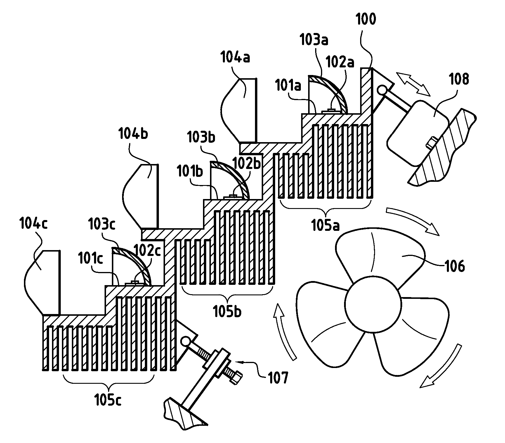
[0015] The use according to the invention of anisotropic graphite, in particular a graphite in a lamellar structure, allows the production of compact and lightweight lighting and / or signaling devices, while satisfying the thermal constraints imposed on power light emitting diodes. This result is made possible in particular because of the superior characteristics of anisotropic graphite compared with aluminum, in terms of density and thermal conductivity, and through the high thermal anisotropy presented by this material. This thermal anisotropy allows the design of heat screens vis-à-vis heat sources, such as filament lamps, situated close to the diodes.

Problems solved by technology

The integration of power LED diodes in headlights and signaling lights does however pose difficulties and new constraints relating to the necessity for efficient thermal management in a relatively confined environment represented by the internal volume of a headlight or signaling light.
These thermal management constraints are particularly difficult to overcome in the case of a headlight, in particular because of the location thereof partly in the engine compartment of the vehicle and the lighting powers concerned.
These known solutions may lead to heat sinks of significant volume and weight that make it tricky to design modern lighting / signaling devices in which new functions of the AFS type are to be installed.

Method used


Image

  • Lighting and/or signaling device for a motor vehicle incorporating a material having thermal anisotropy
  • Lighting and/or signaling device for a motor vehicle incorporating a material having thermal anisotropy
  • Lighting and/or signaling device for a motor vehicle incorporating a material having thermal anisotropy

Examples


Embodiment Construction

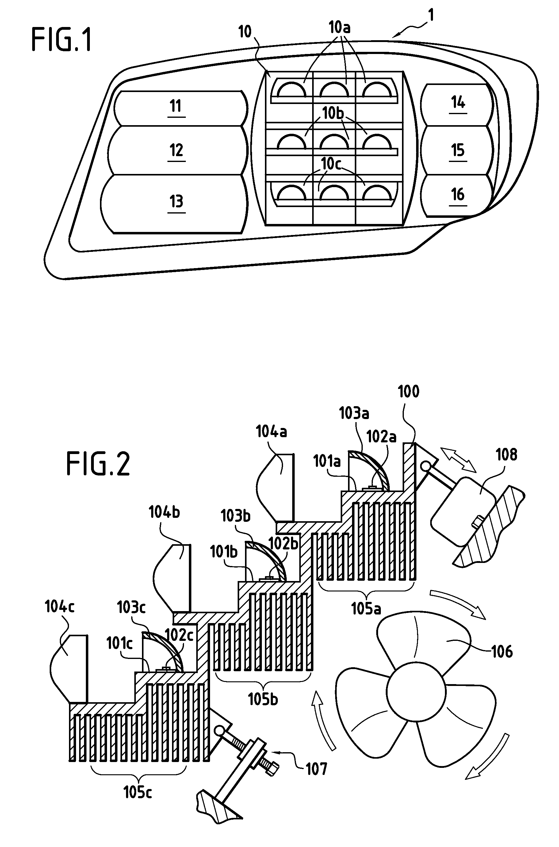
[0037] With reference essentially to FIGS. 1 to 3, a description is now given of a first particular embodiment, designated overall 1, of a lighting and / or signaling device such as a headlight according to the invention.

[0038] In this particular embodiment, the headlight 1 comprises light sources of various types, namely power light emitting diodes and incandescent lamps. These various light sources are included in lighting and signaling modules 10 to 16 of the headlight 1, modules that will be shown in front view in FIG. 1.

[0039] In this example, the lighting module 10 is a dipped / main beam lighting module comprising nine power LED diodes emitting a white light.

[0040] The modules 11 to 16 are lighting modules and signaling modules fulfilling functions such as fog lighting, change of direction blinking indicator, daytime lighting (DRL, standing for “day running light” in English) and AFS functions such as fixed bending dipped beam, motorway lighting and the like.

[0041] In a varia...


PUM


Abstract

The device comprises at least one power light emitting diode light source and other means able to constitute one or more heat sources of such a nature as to affect the thermal environment of the light emitting diode light source. In accordance with the invention, the device also comprises a support piece formed at least partially from a material based on anisotropic graphite supporting the light emitting diode light source and opposing an effect of the other means on the thermal environment of the light emitting diode light source. According to other characteristics, the support piece comprises at least one thermal dissipation heat sink and the device can comprise a fan able to force a circulation of air through the heat sink.

Description

BACKGROUND OF THE INVENTION [0001] 1. Field of the Invention [0002] The invention concerns in general terms lighting and / or signaling devices intended to be mounted in motor vehicles. More particularly, the invention concerns lighting and / or signaling devices for a motor vehicle comprising at least one power light emitting diode light source and other means able to constitute one or more heat sources of such a nature as to affect the thermal environment of the power light emitting diode light source. [0003] 2. Description of the Related Art [0004] Recent technological developments in the field of white power light emitting diodes make more and more probable a rise in power in the use of these light sources for performing lighting and signaling functions in a vehicle. [0005] With regard to technical performance, power light emitting diodes, referred to as “power LEDs”, have undeniable strengths making them particularly attractive in a certain number of applications. With regard to th...

Claims


Application Information

Patent Timeline
IPC IPC(8): F21V29/02F21S8/10B60Q1/06F21V29/15
CPCB60Q1/0041F21V29/767B60Q1/1415F21S48/1159F21S48/1747F21S48/32F21S48/325F21S48/328F21V25/00F21V29/004F21V29/02F21Y2101/02F28D2021/0029F28F21/02B60Q1/076F21V29/75F21V29/763B60Q1/10F21V29/74F21Y2115/10F21S41/148F21S41/151F21S41/663F21S43/14F21S45/43F21S45/47
Inventor NICOLAI, JEAN-MARC
Owner VALEO VISION SA
Learn More