
Method and apparatus for controlling rotation speed of fan

a technology of rotation speed and fan, which is applied in the direction of electrical apparatus, cooling/ventilation/heating modification, and modifications using gaseous coolants, etc. it can solve the problems of large amount of heat produced by the cpu or even the computer system, and noise produced by the high rotation speed so as to reduce the noise of the cooling fan, automatically control the rotation/operation speed, and reduce the effect of nois

Inactive Publication Date: 2007-04-05
HON HAI PRECISION IND CO LTD
View PDF3 Cites 32 Cited by
  • Summary
  • Abstract
  • Description
  • Claims
  • Application Information

AI Technical Summary

Benefits of technology

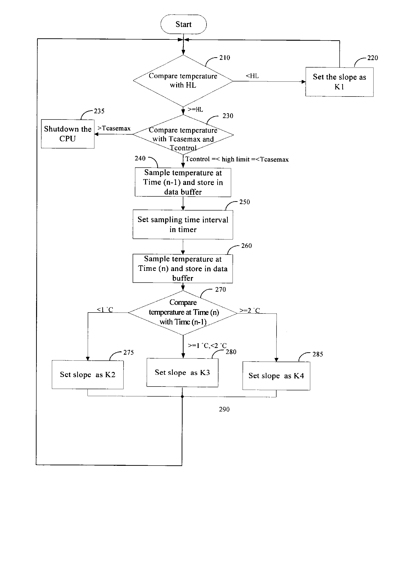
[0006] A method and an apparatus for automatically controlling rotation / operation speed of a cooling fan are provided. In a preferred embodiment, the method includes the following steps: Sampling temperature values of the electronic component at Time (n−1) and at Time (n). Then storing those temperature values. Then comparing the temperature value Time (n−1) with Time (n). And then setting the rotation speed of the cooling fan according to the comparison result. The present invention can not only automatically control the rotation speed of a cooling fan, but also reduce the noise of the cooling fan during those times when maximum cooling is not needed.

Problems solved by technology

Especially, the CPU produces a large amount of heat.
If the heat generated from the CPU is not dissipated in a timely fashion, it may damage the CPU or even the computer system.
However, high rotation speeds of the cooling fan will produce a lot of noise.
As shown FIG. 6, the temperature of the CPU meets with the CPU thermal profile, but the power of the cooling fan is wasted and may lead to a lot of noise.

Method used


Image

  • Method and apparatus for controlling rotation speed of fan
  • Method and apparatus for controlling rotation speed of fan
  • Method and apparatus for controlling rotation speed of fan

Examples


Embodiment Construction

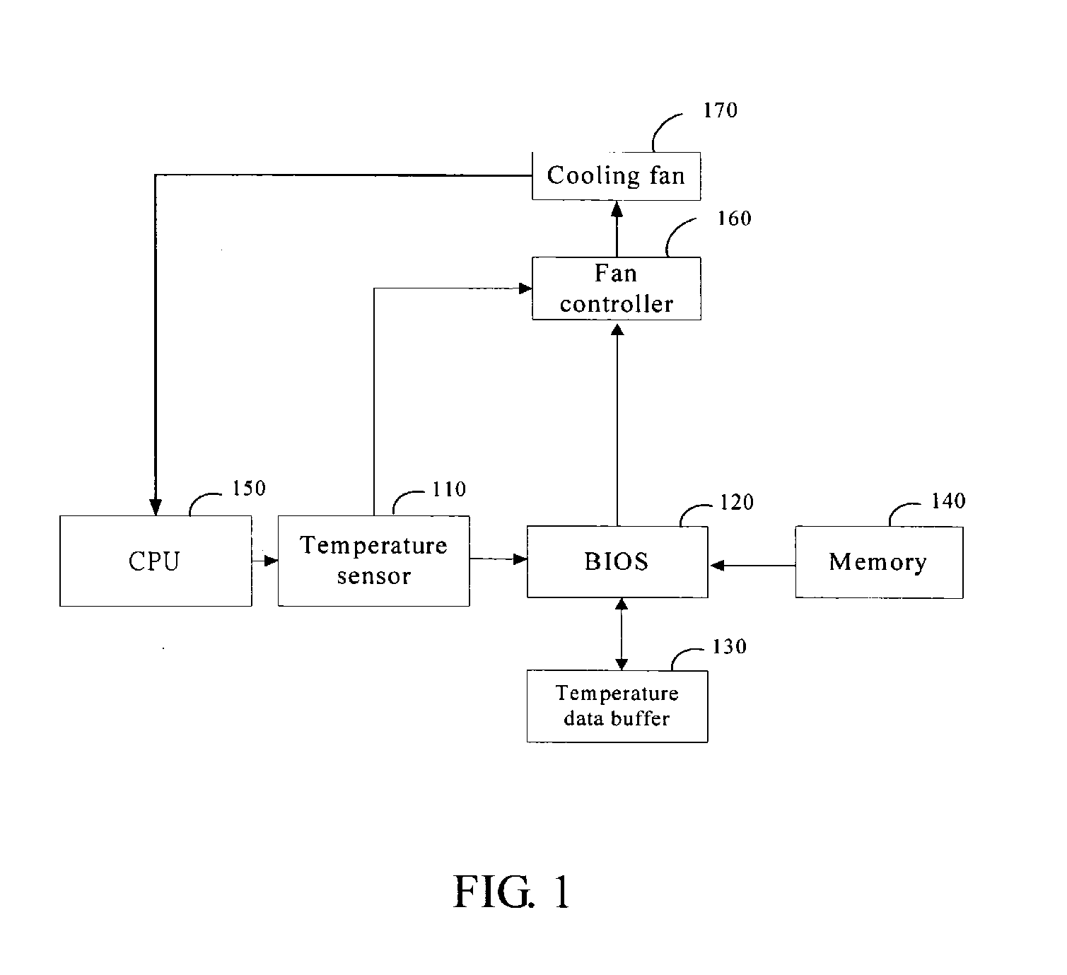
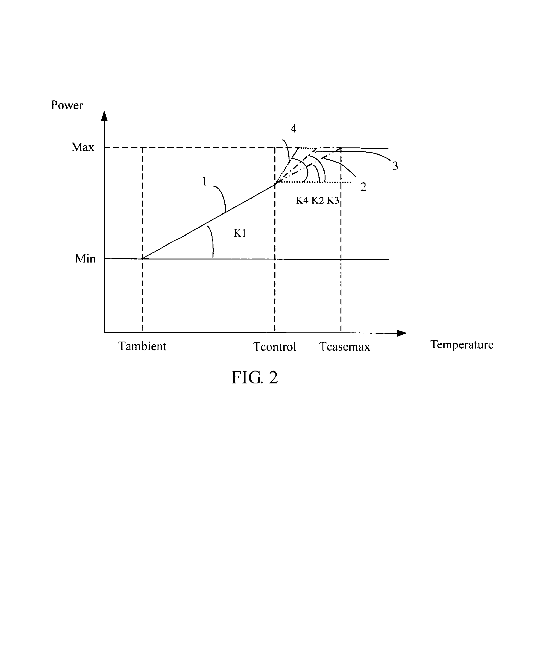
[0014] Referring to FIG. 1, a schematic diagram of an apparatus for controlling the rotation / operation speed of a cooling fan 170, in accordance with a preferred embodiment of the present invention is shown. The apparatus includes a temperature sensor 110. The temperature sensor 110 is used to detect temperatures of an electronic component, such as a CPU 150, that is the object to be cooled by the cooling fan 170. The temperature values are input to a basic input output system (BIOS) 120 and stored in a temperature data buffer 130. In the BIOS 120, interruptions are generated by a system management interruption (SMI). The SMI is triggered by the temperature value from the temperature sensor 110. In the BIOS 120, a control program is stored for determining how much power should be supplied to the cooling fan 170 according to the magnitude of the rate of change of the temperature of the CPU 150. The control program is executed when the SMI is triggered. A number of slopes are predeter...


PUM


Abstract

A method and an apparatus for automatically controlling rotation speed of a cooling fan are provided. The method includes the following steps: Sampling temperature values of the electronic component at Time (n−1) and at Time (n). Then storing the temperature values at Time (n−1) and at Time (n). Then comparing the temperature vale at Time (n−1) with that at Time (n). And then setting the rotation speed of the cooling fan according to the comparison result in the last step. The present invention can not only automatically control the rotation speed of a cooling fan, but also reduce the noise of the cooling fan.

Description

FIELD OF THE INVENTION [0001] The present invention relates to a method and an apparatus for controlling operation / rotation speed of a fan, and particularly to a method and an apparatus for automatically controlling the operation (rotation) speed of a CPU cooling fan. DESCRIPTION OF RELATED ART [0002] Generally, a computer system includes a motherboard with various chips such as a central processing unit (CPU) mounted thereon, a storage device such as a hard disc, and input / output devices, each of which is known to generate heat when operated in a computer system. Especially, the CPU produces a large amount of heat. If the heat generated from the CPU is not dissipated in a timely fashion, it may damage the CPU or even the computer system. Developments in today's highly information-intensive society have led to remarkable improvements in performances of electronic devices. A cooling fan is used to facilitate removal of heat to keep a temperature of the CPU within a safe temperature r...

Claims


Application Information

Patent Timeline
IPC IPC(8): H05K7/20
CPCH05K7/20209
Inventor LIN, WEN-HSIANG
Owner HON HAI PRECISION IND CO LTD
Learn More