Magnetic sensor and current sensor

Active Publication Date: 2007-04-05
TDK CORPARATION
View PDF2 Cites 83 Cited by
  • Summary
  • Abstract
  • Description
  • Claims
  • Application Information

AI Technical Summary

Benefits of technology

[0007] The present invention has been achieved in consideration of such problems, and it is desirable to provide a more miniaturized and simple current sensor capable of measuring a current to be detected with high precision and stability.
[0022] According to the method of manufacturing the magnetic sensor of an embodiment of the present invention, after grinding the back of a substrate provided with a plurality of magnetoresistive elements are formed, a magnetic sheet is stuck on the back of the substrate, then a magnetization direction of the magnetic sheet is set and after that, the laminated product is cut to divide into pieces so that each piece includes a magnetoresistive element. In this manner, there is an effect that a plurality of magnetic sensors having a magnetoresistive element to which a bias magnetic field is applied in a direction can be formed at a time and in a simple and easy way.

Problems solved by technology

In this case, however, a load different from the control system is given, and there is a possibility that an adverse influence may be exerted on the control system.
However, the above-described current sensor has problems that a miniaturization is difficult and that the linearity of detection sensitivity to the change of magnetic field or high-frequency response are inadequate and so on.

Method used


Image

  • Magnetic sensor and current sensor
  • Magnetic sensor and current sensor
  • Magnetic sensor and current sensor

Examples


first embodiment

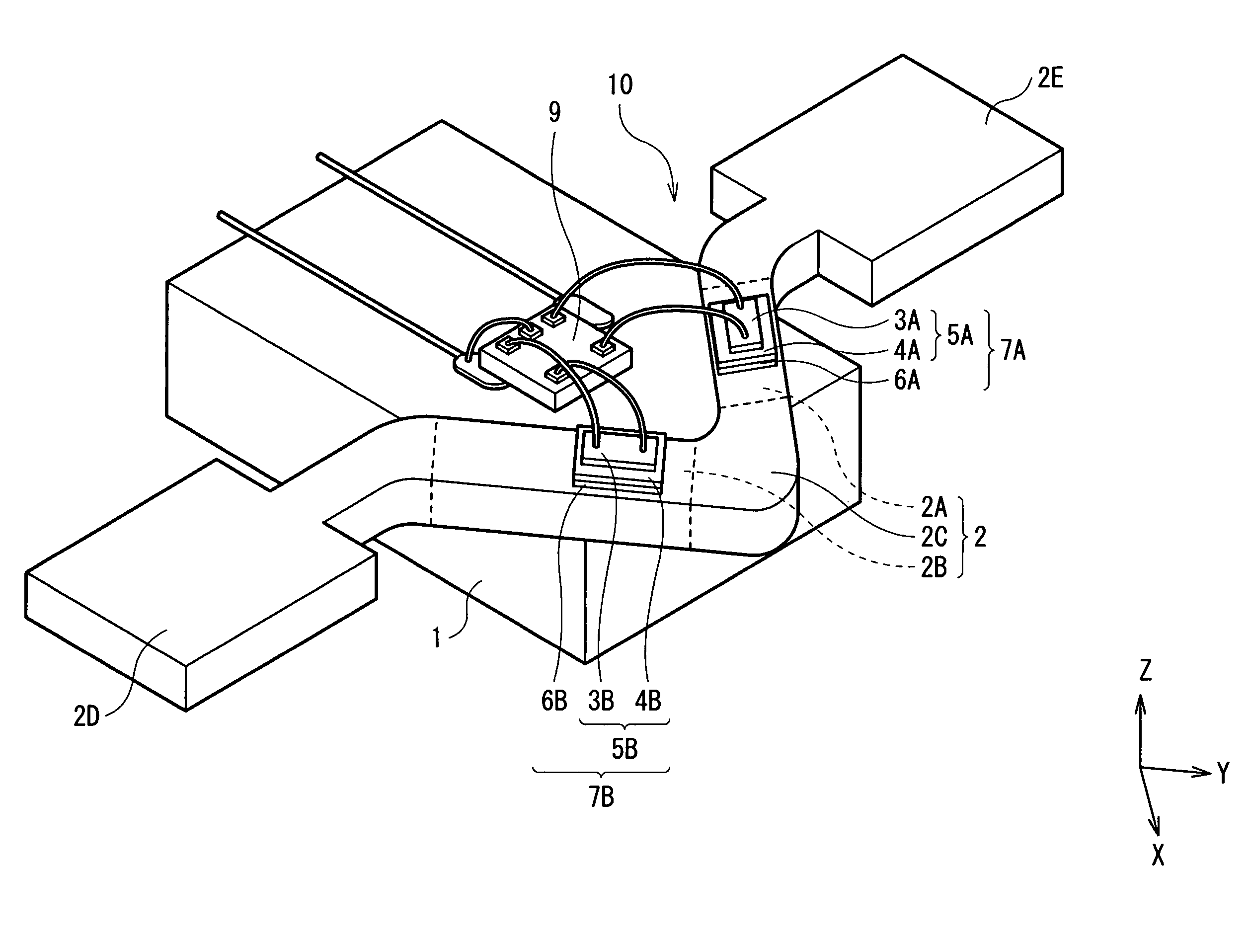
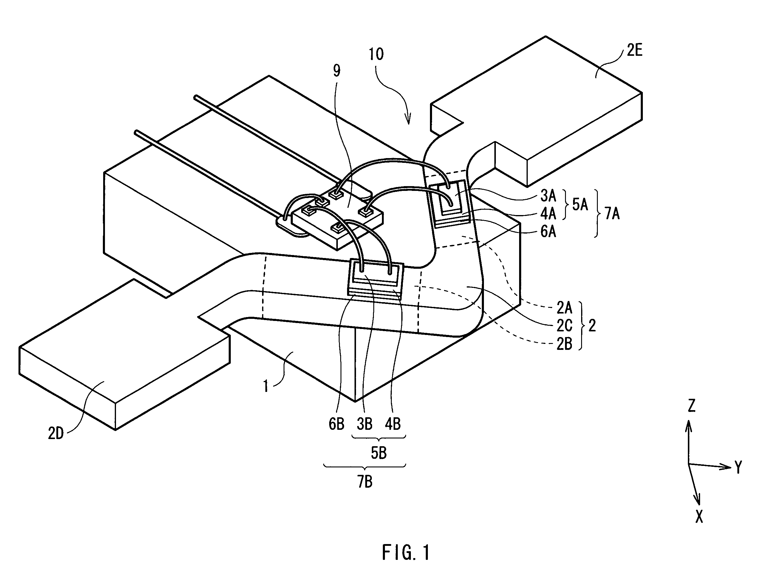
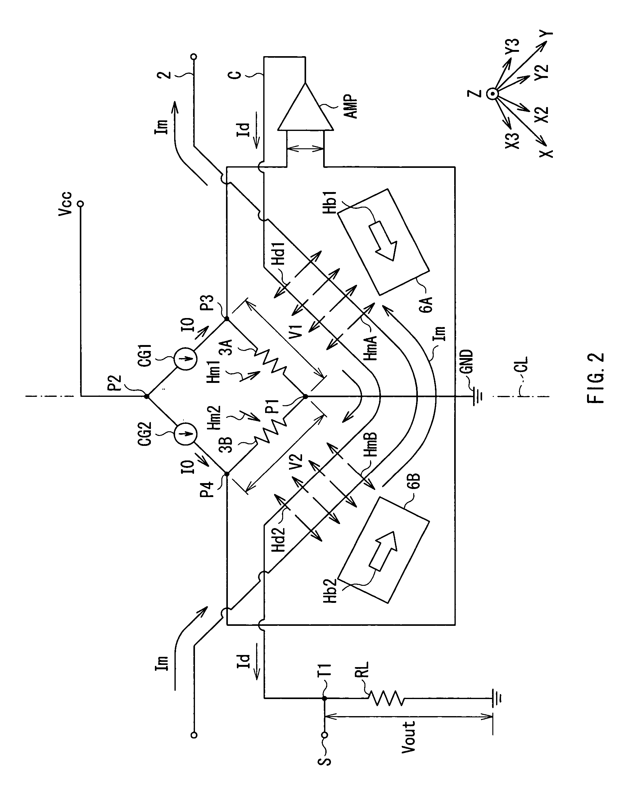
[0046] First, a configuration of a current sensor according to a first embodiment of the present invention will be explained with reference to FIG. 1 and FIG. 2. FIG. 1 is a schematic diagram showing a perspective configuration of a current sensor 10 according to the present embodiment, and FIG. 2 expresses a circuit configuration of the current sensor 10 appearing in FIG. 1. Directions of all the arrows in FIG. 2 representing a current to be detected Im, a compensating current Id, current magnetic fields HmA and HmB, compensating current magnetic fields Hd, bias magnetic fields Hb1 and Hb2, and a current 10 indicate a relative direction with respect to a first and a second magnetoresistive elements 3A and 3B (which will be described later).

[0047] The current sensor 10 is an ammeter for measuring a current to be detected Im supplied to a conductor 2 formed on a substrate 1, and is provided with magnetic sensors 7A and 7B including a first and second magnetoresistive elements 3A and...

second embodiment

[0080] A current sensor as a second embodiment according to the present invention will be explained next. Although in the foregoing first embodiment is explained the case in which the conductor line 2 of V-shaped configuration in plan view is used, in the present embodiment is explained a case in which a straight-line shaped conductor line 21 is employed.

[0081] Since the current sensor of the present embodiment has the same configuration as that of the above-mentioned first embodiment substantially except for the conductor line 21, here is explained the relation among the magnetization directions J11 and J13 of the GMR films in the MR elements 3A and 3B, the bias magnetic field Hb, and the current magnetic field Hm with reference to FIGS. 11A and 11B. FIGS. 11A and 11B are conceptual diagrams about the relation among the current direction, the magnetic field direction, and the magnetization direction according to the current sensor of the present embodiment. Here, a current to be d...

third embodiment

[0086] Next, a current sensor as a third embodiment according to the present invention will be explained. In the first embodiment as described above is explained the case of arranging the two MR elements 3A and 3B on the straight-line portions 2A and 2B of the conductor line 2. On the other hand, in the present embodiment, four MR elements 3A-3D are arranged on one conductor line 2. Explanation will be made hereinbelow with reference to FIG. 13. Since its configuration is substantially similar to that of the above-mentioned first embodiment except for the point that the four MR elements 3A-3D are arranged, descriptions will be omitted suitably according to circumstances.

[0087]FIG. 13 is a conceptual diagram showing the relation among the current direction, magnetic field direction, and magnetization direction of the current sensor according to the present embodiment. As shown in FIG. 13, in the current sensor of the present embodiment, the straight-line portion 2A is provided with ...


PUM


Abstract

The present invention provides a current sensor of smaller and simpler configuration, capable of measuring a current to be detected with high precision and stability. A magnetic sensor includes: an element substrate including a magnetoresistive element, the magnetoresistive element having a pinned layer with a magnetization pinned to a direction, an intermediate layer, and a free layer whose magnetization direction changes according to an external magnetic field; and a magnetic sheet attached on one side of the element substrate so as to apply a bias magnetic field to the magnetoresistive element.

Description

BACKGROUND OF THE INVENTION [0001] 1. Field of the Invention [0002] The present invention relates a magnetic sensor capable of detecting a variation of a magnetic field with high sensitivity, and a current sensor capable of detecting a variation of a current flowing through a conductor line with high sensitivity. [0003] 2. Description of the Related Art [0004] In measuring correctly a control current which flows into a circuit of control equipment, a method where resistances are connected in series within the circuit to measure a voltage drop of the resistances is applied generally. In this case, however, a load different from the control system is given, and there is a possibility that an adverse influence may be exerted on the control system. Consequently, a method of indirectly measuring a control current by detecting the gradient of a current magnetic field generated by the control current has been used. Specifically, a control current is supplied to a U-shaped, curved conductor...

Claims


Application Information

Patent Timeline
IPC IPC(8): G11B5/127G11B5/33
CPCB82Y25/00G01R15/205G01R33/09H01F10/3281H01L2224/48091H01L2224/48247H01L2224/05554H01L2224/48137H01L2224/48257H01L2924/00014
Inventor SHOJI, SHIGERUTAKAHASHI
Owner TDK CORPARATION
Why Eureka
Try Eureka