
System and method for compensating for radiation induced thermal distortions

a radiation-induced thermal distortion and radiation-induced distortion technology, applied in the field of lithographic equipment, can solve the problems of thermal distortion, reducing the quality of the image formed on the substrate, and reducing the overlay accuracy between pattern layers

Active Publication Date: 2007-04-05
ASML NETHERLANDS BV
View PDF46 Cites 30 Cited by
  • Summary
  • Abstract
  • Description
  • Claims
  • Application Information

AI Technical Summary

Benefits of technology

[0011] In another embodiment of the present invention, there is provided a method of producing a compensated dose pattern for lithography comprising the following steps. Modeling an expected distortion to a pattern formed on a substrate by a radiation beam that has been modulated according to a desired dose pattern, the distortion arising due to the thermal effects that the modulated radiation beam would have on a projection system during projection. Calculating a compensated dose pattern to counteract the expected distortion, defined so that when the radiation beam is modulated according to the compensated dose pattern, the pattern formed on the substrate is closer to the desired dose pattern.
[0012] In a further embodiment of the present invention, there is provided a method of producing a compensated dose pattern for lithography comprising the following steps. Modeling an expected distortion to a pattern formed on a substrate by a modulated radiation beam that has been modulated according to a desired pattern, the distortion arising due to the thermal effects that the modulated radiation beam would have on the substrate when projected thereon. Calculating a compensated dose pattern to counteract the expected distortion, defined so that when the radiation beam is modulated according to the compensated dose pattern, the pattern formed on the substrate is closer to the desired dose pattern. The desired pattern to be formed on the substrate is defined relative to a plurality of reference points on the substrate. The modeling takes into account thermally-induced changes to the relative positions of the reference points and the compensated radiation beam is produced by interpolation between the reference points.

Problems solved by technology

The projection beam can transfer heat to the substrate and / or projection system during exposure, leading to thermal distortion.
Distortion during exposure can reduce the quality of the image formed on the substrate (for example, reducing overlay accuracy between pattern layers and reducing critical dimension uniformity).

Method used


Image

  • System and method for compensating for radiation induced thermal distortions
  • System and method for compensating for radiation induced thermal distortions
  • System and method for compensating for radiation induced thermal distortions

Examples


Embodiment Construction

[0029] While specific configurations and arrangements are discussed, it should be understood that this is done for illustrative purposes only. A person skilled in the pertinent art will recognize that other configurations and arrangements can be used without departing from the spirit and scope of the present invention. It will be apparent to a person skilled in the pertinent art that this invention can also be employed in a variety of other applications.

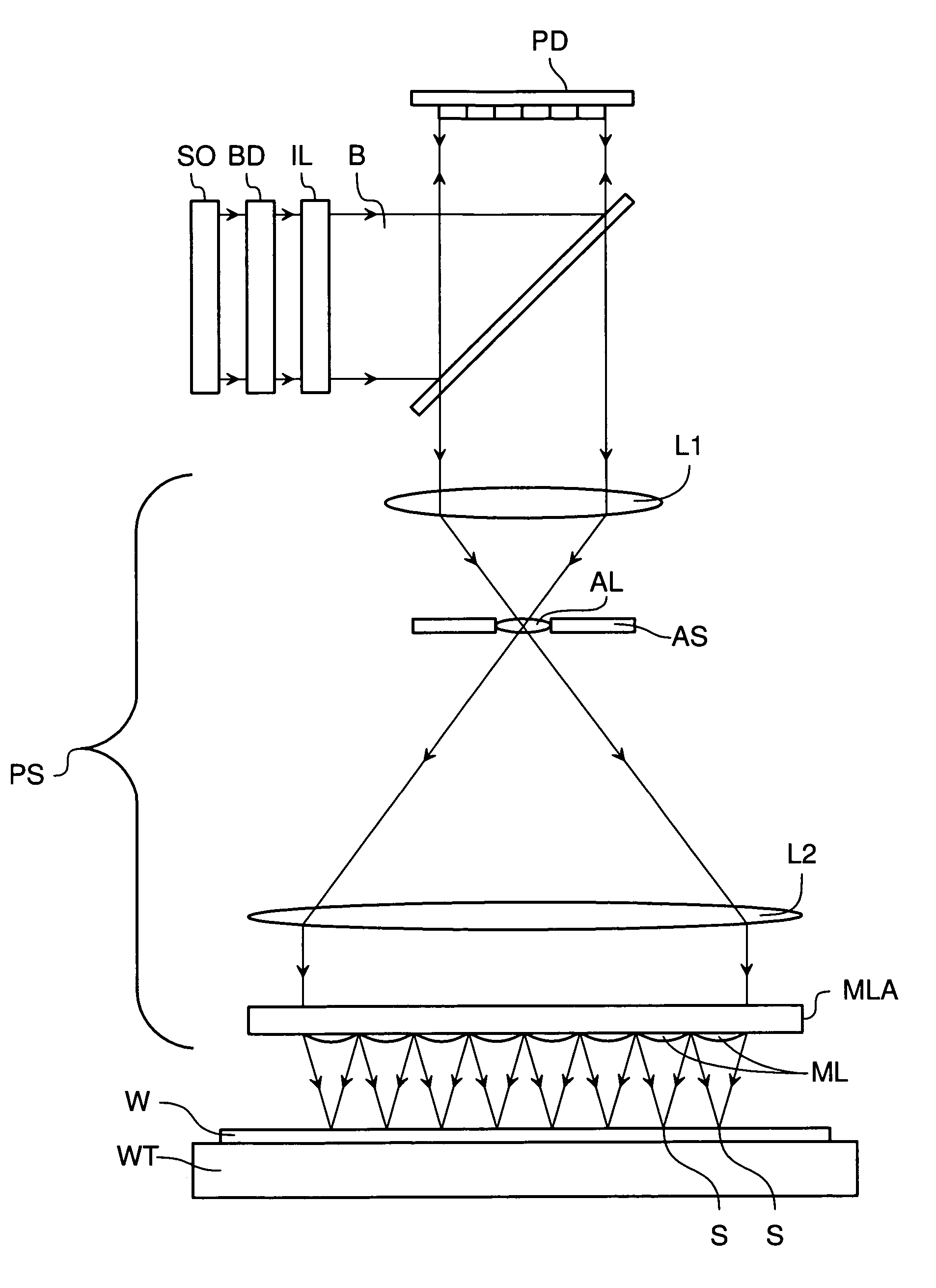
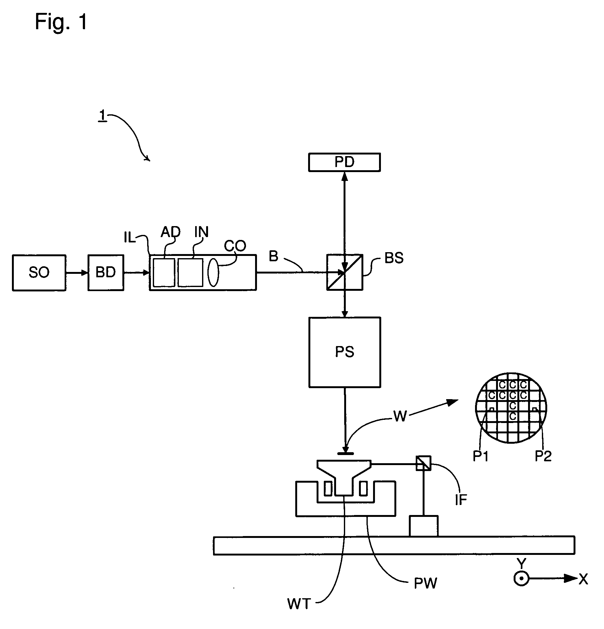
[0030]FIG. 1 schematically depicts the lithographic apparatus of one embodiment of the invention. The apparatus comprises an illumination system IL, a patterning device PD, a substrate table WT, and a projection system PS.

[0031] The illumination system (illuminator) IL is configured to condition a radiation beam B (e.g., UV radiation).

[0032] The patterning device PD (e.g., a reticle or mask or an array of individually controllable elements) modulates the beam. In general, the position of the array of individually controllable elem...


PUM


Abstract

A system and method are used to compensate for thermal effect on a lithographic apparatus. The system comprises a patterning device, a projection system, a substrate position controller, and a substrate-position-based expansion-compensator. The patterning device modulates a radiation beam. The projection system projects the modulated radiation beam onto a target portion of a substrate. The substrate position controller moves the substrate relative to the projection system sequentially through a plurality of exposure positions. The substrate-position-based expansion-compensator interacts with the substrate position controller to modify the exposure positions in order at least partially to compensate for thermally-induced geometrical changes of at least one of the substrate and projection system.

Description

CROSS REFERENCE TO RELATED APPLICATIONS [0001] This application claims benefit under 35 U.S.C. 119(e) to U.S. Provisional Patent Application No. 60 / 722,950, filed Oct. 4, 2005, which is incorporated by reference herein in its entirety.BACKGROUND [0002] 1. Field of the Invention [0003] The present invention relates to a lithographic apparatus and a method for manufacturing a device. [0004] 2. Related Art [0005] A lithographic apparatus is a machine that applies a desired pattern onto a substrate or part of a substrate. A lithographic apparatus can be used, for example, in the manufacture of flat panel displays, integrated circuits (ICs) and other devices involving fine structures. In a conventional apparatus, a patterning device, which can be referred to as a mask or a reticle, can be used to generate a circuit pattern corresponding to an individual layer of a flat panel display (or other device). This pattern can be transferred onto all or part of the substrate (e.g., a glass plate)...

Claims


Application Information

Patent Timeline
Patent Type & Authority Applications(United States)
IPC IPC(8): G03B27/42
CPCG03F7/70725G03F7/70875G03F7/70891G03F7/70858
Inventor TINNEMANS, PATRICIUS ALOYSIUS JACOBUSVENEMA, WILLEM JURRIANUSMARIA ZAAL, KOEN JACOBUS JOHANNES
Owner ASML NETHERLANDS BV
Learn More