Bridge, error notification method therefor and system
- Summary
- Abstract
- Description
- Claims
- Application Information
AI Technical Summary
Benefits of technology
Problems solved by technology
Method used
Image

Examples
first embodiment
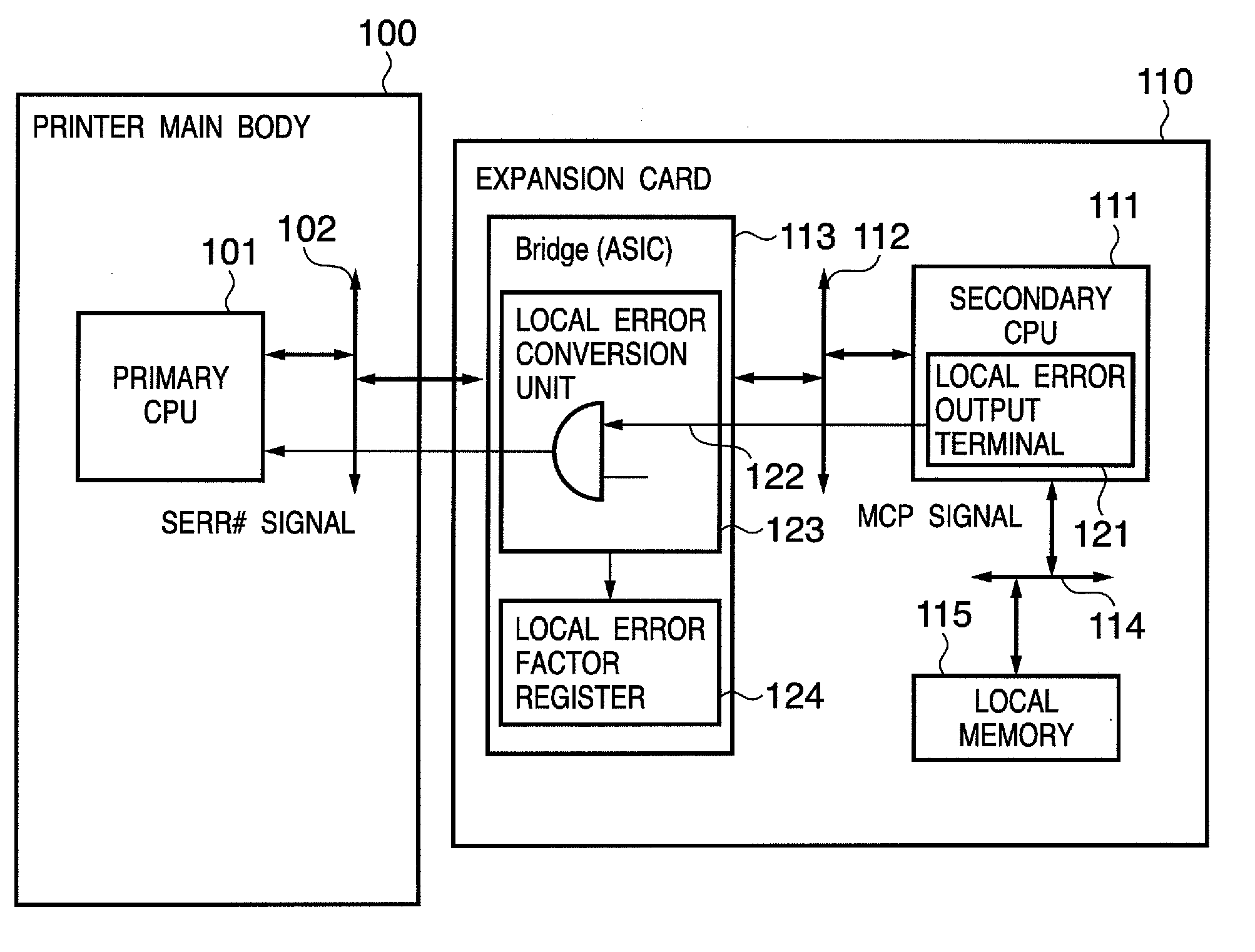
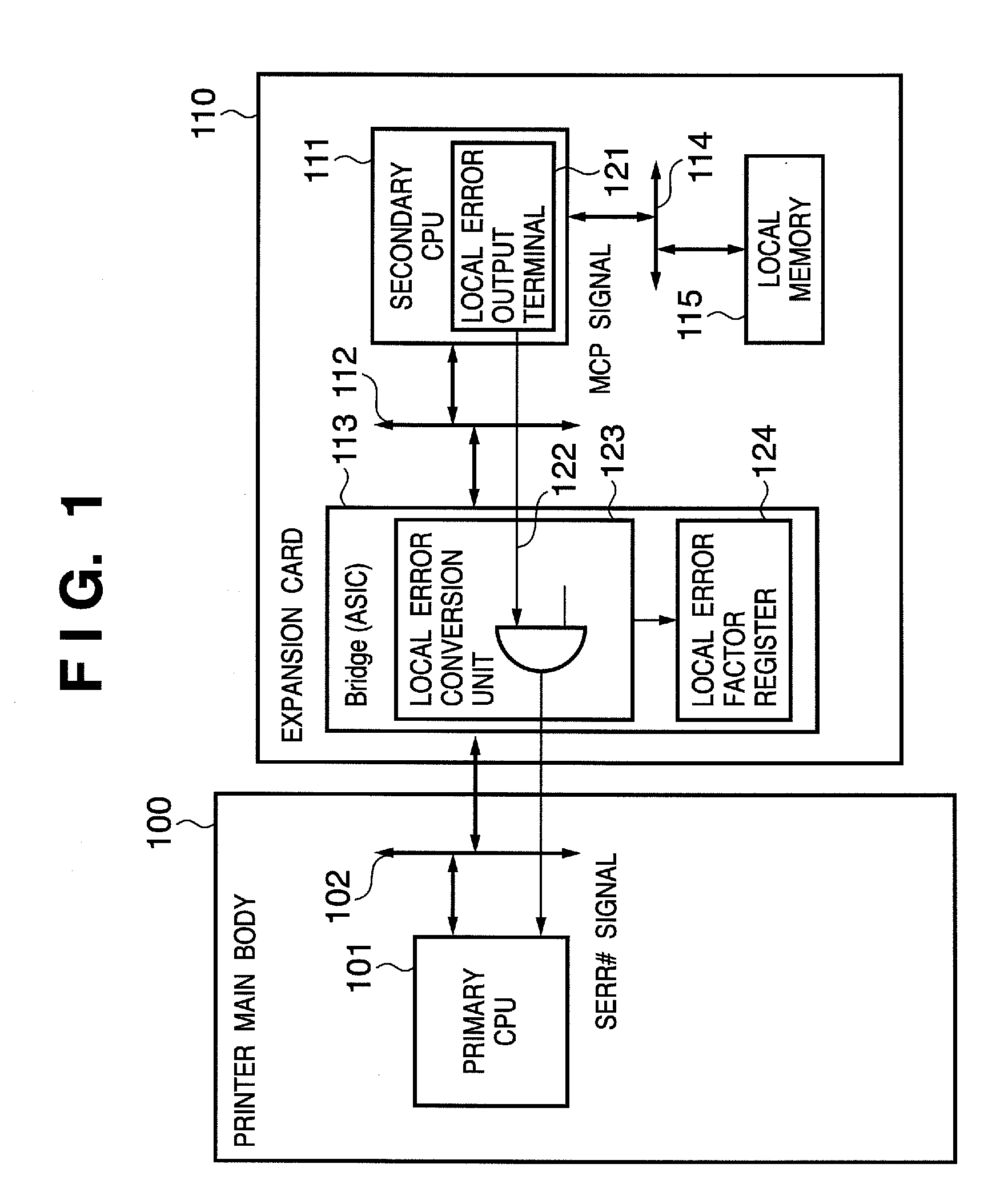
[0020]FIG. 1 is a block diagram showing an example of the configuration of a system using a bridge in the first embodiment. Referring to FIG. 1, reference numeral 100 denotes a printer main body as an example of an apparatus implementing the present invention, which comprises an expansion bus such as a PCI bus and to which an expansion card (to be described later) can be connected. Note that the present invention is not limited to a printer. A function such as a network function, wireless LAN function, and USB HUB function which is not provided for the printer main body 100 can be added to the printer main body 100 by using the expansion card. Reference numeral 101 denotes a primary CPU which controls the overall printer main body 100 in accordance with a program stored in a ROM (not shown). Reference numeral 102 denotes a primary PCI bus as an expansion bus, which provides an interface (I / F) corresponding to a PCI bus.
[0021] Reference numeral 110 denotes an expansion card which is...
second embodiment
[0030] The second embodiment according to the present invention will now be described in detail with reference to the accompanying drawings. In the second embodiment, a register for setting whether to perform a local error notification is provided in addition to the configuration described in the first embodiment.
[0031]FIG. 3 is a block diagram showing an example of the configuration of a bridge 300 in the second embodiment. Referring to FIG. 3, the bridge 300 includes an error enable register 301. With the error enable register 301, a local error notification is output to the primary CPU 101 only when the error enable register 301 is enabled. The bridge 300 is used instead of the bridge 113 in FIG. 1.
[0032] Note that the operation of the expansion card 110 is the same as that in the first embodiment except that the local error conversion unit 123 performs a local error notification only when the error enable register 301 is enabled.
[0033] The error enable register 301 is control...
third embodiment
[0035] The third embodiment according to the present invention will now be described in detail with reference to the accompanying drawings. In the third embodiment, occurrence of a local error is recognized by a watchdog timer.
[0036]FIG. 4 is a block diagram showing an example of the configuration of a system using a bridge in the third embodiment. The local error output terminal 121 is provided within the secondary CPU 111 of the expansion card 110 in the first embodiment shown in FIG. 1, but in the third embodiment, a local error output unit is provided external to a secondary CPU 411. The printer main body 100 and other components within an expansion card 410 are the same as those in the first embodiment. Accordingly, a difference from the first embodiment will be explained.
[0037] In FIG. 4, reference numeral 431 denotes a local error output unit which functions as a watchdog timer and is connected to the local bus 114. The secondary CPU 411 periodically performs a write operat...
PUM
 Abstract
Description
Claims
Application Information
 - R&D
- Intellectual Property
- Life Sciences
- Materials
- Tech Scout
- Unparalleled Data Quality
- Higher Quality Content
- 60% Fewer Hallucinations
Browse by: Latest US Patents, China's latest patents, Technical Efficacy Thesaurus, Application Domain, Technology Topic, Popular Technical Reports.
© 2025 PatSnap. All rights reserved.Legal|Privacy policy|Modern Slavery Act Transparency Statement|Sitemap|About US| Contact US: help@patsnap.com