
Power transmission chain and power transmission assembly using the same

Inactive Publication Date: 2007-03-29
JTEKT CORP
View PDF19 Cites 18 Cited by
  • Summary
  • Abstract
  • Description
  • Claims
  • Application Information

AI Technical Summary

Benefits of technology

[0006] However, the above invention as disclosed in Japanese Unexamined Patent Publication No.S63(1988)-53337 has a drawback that the longer pins are more intensively worn than the shorter pins. That is, the longer pins become shorter as intensively worn so that the length difference between the longer pins and the shorter pins is gradually decreased. As used longer, therefore, the power transmission chain is gradually reduced in noise reduction effect, thus failing to offer an adequate effect. Since the longer pins are subjected to a greater force than the shorter pins, load is concentrated on the longer pins, which are reduced in durability. In addition, a chain assembly process includes management of the pins of different lengths and steps of sorting the pins before assembling the pins. Hence, the number of assembly steps is increased to increase costs.
[0007] The power transmission chain disclosed in Japanese Unexamined Patent Publication No.H8(1996)-312725 reduces the noises during operation by suppressing polygonal vibrations resulting from its structure, which is not constituted by a single continuous body but is formed by interconnecting the plural links. In cases where, for example, a continuously variable transmission using this power transmission chain is mounted in an automotive vehicle, the vehicle is required to further reduce the noises of the power transmission chain for achieving the highest possible silence performance during drive.
[0008] In view of the foregoing, the invention has been accomplished and has an object to provide a power transmission chain capable of effectively reducing the noises.

Problems solved by technology

However, the above invention as disclosed in Japanese Unexamined Patent Publication No.S63(1988)-53337 has a drawback that the longer pins are more intensively worn than the shorter pins.
As used longer, therefore, the power transmission chain is gradually reduced in noise reduction effect, thus failing to offer an adequate effect.
Hence, the number of assembly steps is increased to increase costs.

Method used


Image

  • Power transmission chain and power transmission assembly using the same
  • Power transmission chain and power transmission assembly using the same
  • Power transmission chain and power transmission assembly using the same

Examples


Embodiment Construction

[0051] The preferred embodiments of the invention will hereinbelow be described with reference to the accompanying drawings.

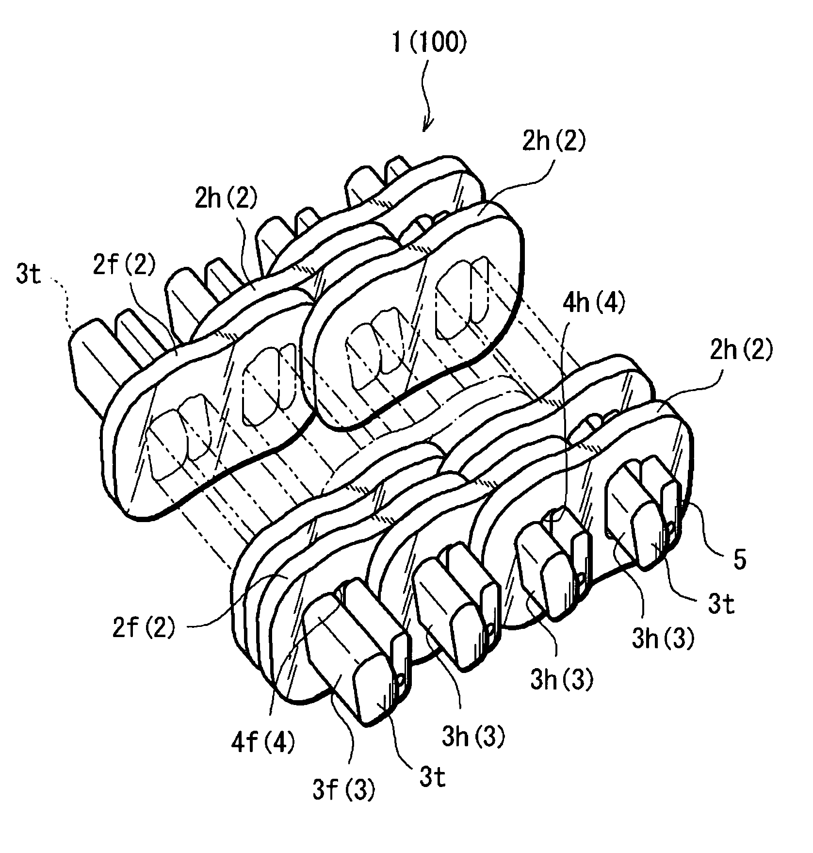
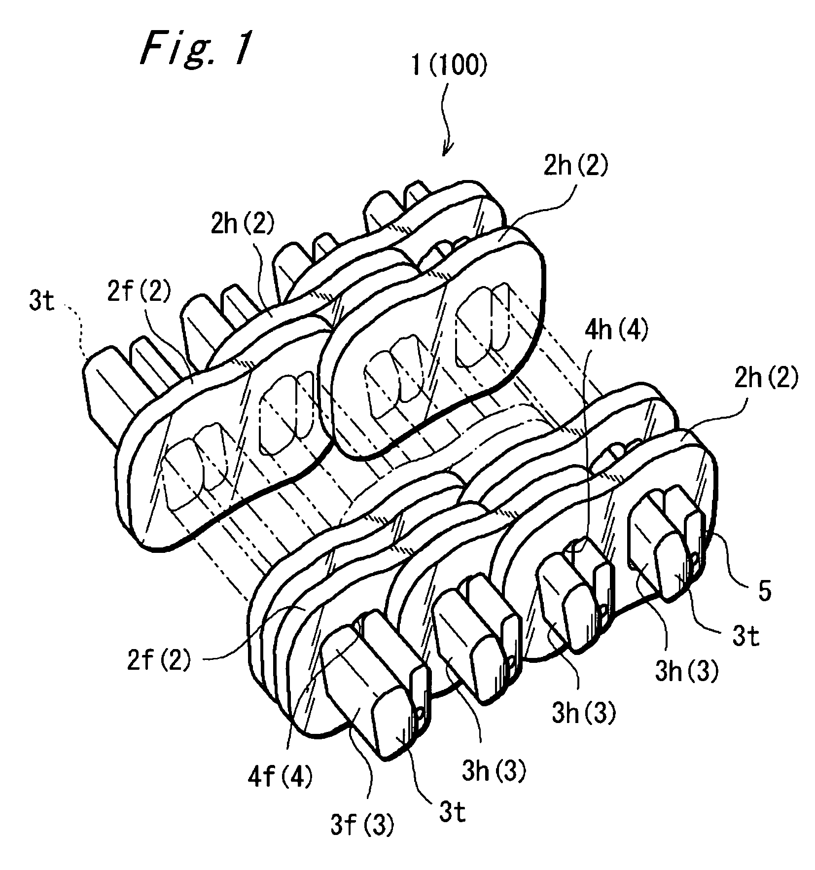
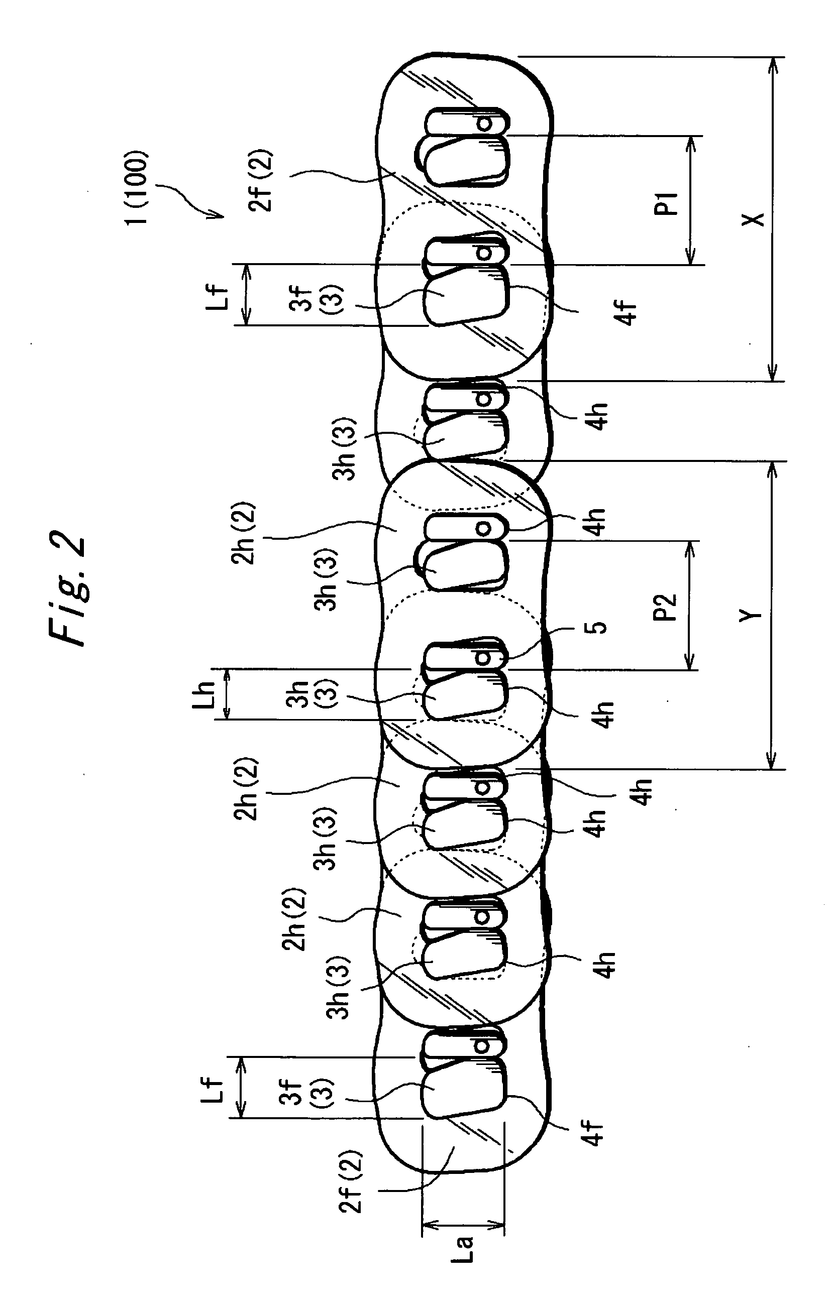
[0052]FIG. 1 is a perspective view schematically showing an essential part of a chain for use in a chain-type continuously variable transmission (hereinafter, simply referred to as “chain”) according to one embodiment of a first aspect of the invention. A chain 1 according to the embodiment is generally shaped like an endless belt and includes: a plurality of metallic links 2; a plurality of metallic pins 3 for interconnecting these links 2; and a plurality of strips 5 slightly shorter than the pins 3 with respect to a pin longitudinal direction. The links 2 and pins 3 are formed from a metal such as a bearing steel. FIG. 1 omits the depiction of some links substantially defining a widthwise central portion of the chain 1.

[0053] As shown in FIG. 1, FIG. 6 and FIG. 7, an individual link 2 has an outside shape formed by a substantially rectangular sheet member ...


PUM


Abstract

An object of the invention is to provide a power transmission chain capable of effectively reducing noises and a power transmission assembly using the same. In the power transmission chain including plural links each possessing through-holes and plural pins inserted through the through-holes for interconnecting the plural links, all the plural pins substantially have the same longitudinal length while the plural pins include plural types of pins which have mutually different rigidities against force acting in the pin longitudinal direction. Furthermore, a locus of contact position between the pin and a strip is defined by an involute of a circle. The pins and strips are combined to form two or more types of pairs which provide the involutes of base circles having different radii.

Description

TECHNICAL FIELD [0001] The present invention relates to a power transmission chain for use in a continuously variable transmission for vehicles, and to a power transmission assembly using the same. BACKGROUND ART [0002] One type of continuously variable transmission (CVT) for automotive vehicles includes, for example: a drive pulley disposed on an engine side; a driven pulley disposed on a drive-wheel side; and an endless-belt-like chain entrained between these pulleys. One type of the power transmission chain includes: a plurality of links; and a plurality of pins for interconnecting these links. Such a continuously variable transmission of a so-called chain type transmits power by way of traction produced from contact friction force between sheave surfaces and end faces of the pins of the chain, the sheave surfaces defined by two conical surfaces disposed internally of each pulley as substantially opposed each other. An alternative continuously variable transmission has an arrange...

Claims


Application Information

Patent Timeline
IPC IPC(8): F16G5/16F16G13/04F16G13/02F16G5/18F16H9/16
CPCF16H9/16F16G5/18F16H9/24
Inventor KAMAMOTO, SHIGEOFUKUI, NOBUKIYASUHARA, SHINJIKITAMURA, KAZUHISA
Owner JTEKT CORP
Learn More