
Protocol extension for a high density network

Active Publication Date: 2007-03-29
CISCO TECH INC
View PDF4 Cites 96 Cited by
  • Summary
  • Abstract
  • Description
  • Claims
  • Application Information

AI Technical Summary

Benefits of technology

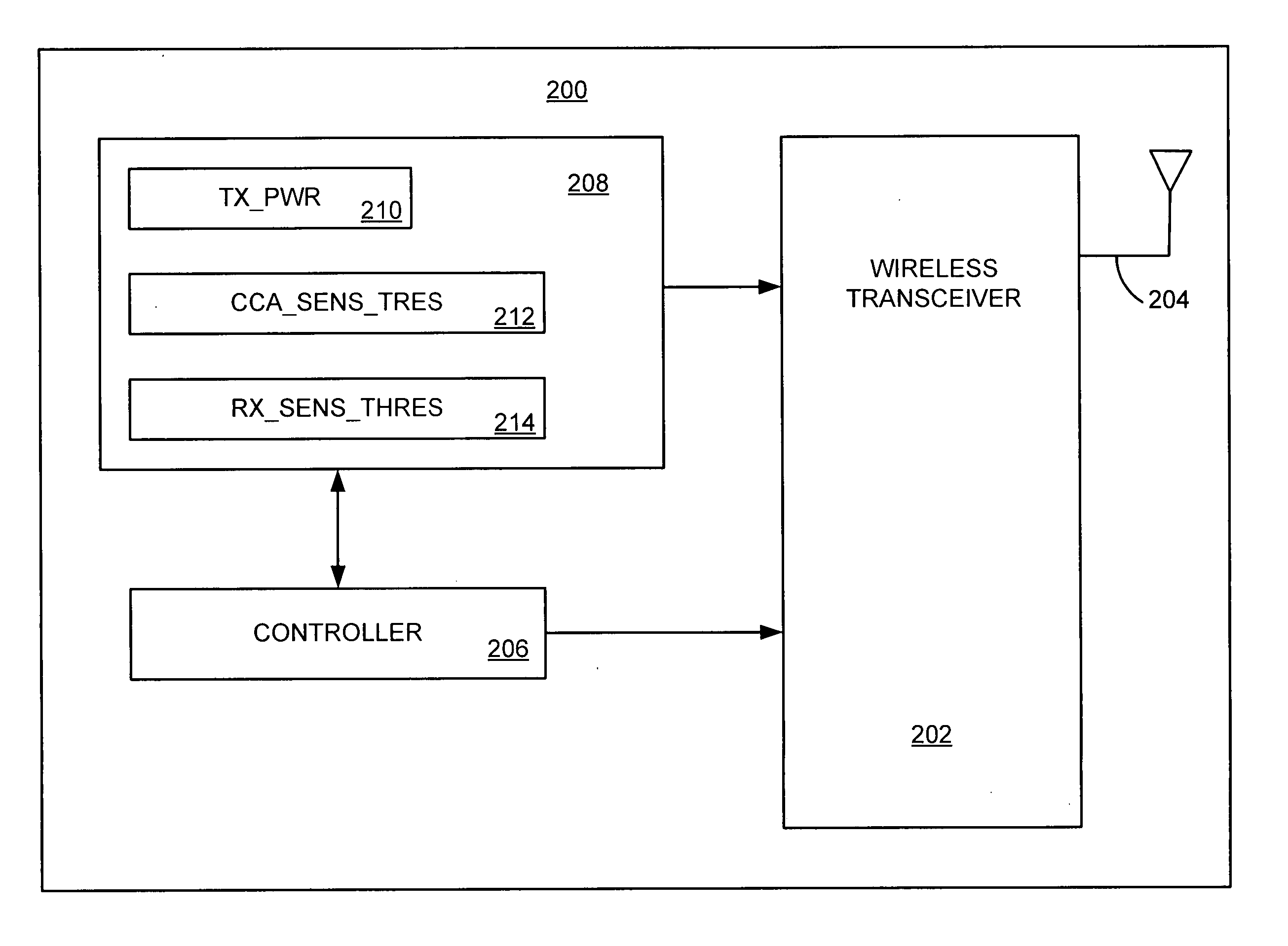
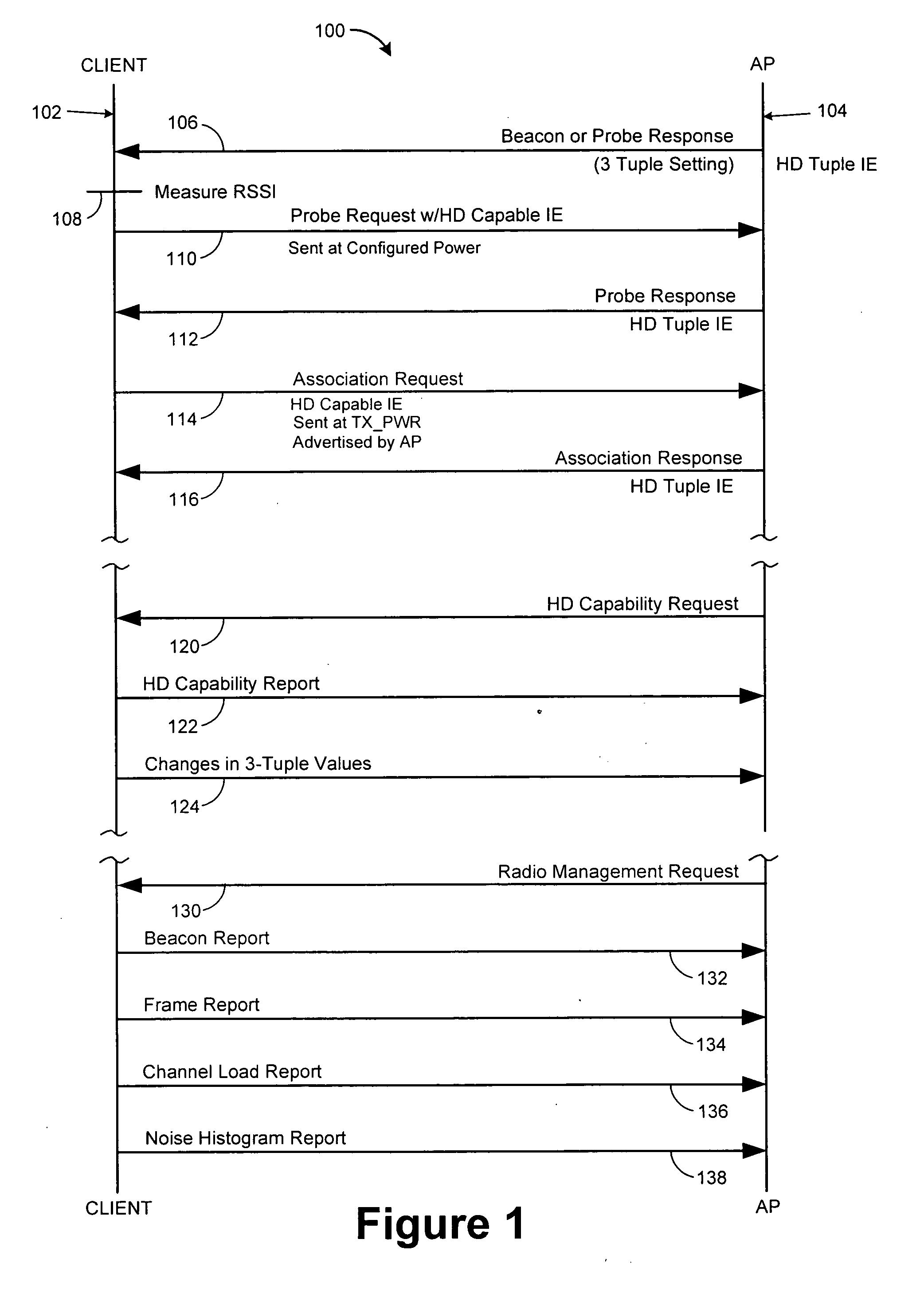
[0007] In accordance with an aspect of the present invention, the present invention solves the communication problem for an IEEE 802.11 WLAN with a High Density infrastructure (network of access points) with High Density clients (stations) while allowing co-existence with non-High Density clients overlapping and / or associated to the High Density network. An aspect of the present invention defines a set of new Information Elements (IEs) to be used between a High Density Access Point (HD AP) and Client (HD Client). These information elements allow a HD AP to advertise its HD capacity (and / or configuration / parameters) to nearby clients, allowing the clients to tune these parameters prior, during and / or after associating with the HD AP and to adjust the HD operating parameters after the client has associated to the HD AP.
[0013] An aspect of the present invention is that it allows a mixture of High Density clients and traditional non-High Density clients to operate in the High Density network (backward compatibility). Another aspect of the present invention is that it provides the flexibility to adjust High-Density operating parameters for a portion or the entire high density network. Still another aspect of the present invention is that it provides flexibility to change the operating parameters after clients have associated to the High Density Network.

Problems solved by technology

Although reducing the transmit power even lower (than 1 mW) may seem a reasonable approach to reducing (configurable) cell sizes even further, radio development issues may become critical (which are outside the scope of this application) and therefore, this cell size adjustment means may be considered undesirable.
Then, an increase in the multi-cell density for such larger networks effectively worsens the RF channel contention problem as a result of the increased number of co-channel (contending) stations present and the excessive inter-cell coverage overlap that occurs.

Method used


Image

  • Protocol extension for a high density network
  • Protocol extension for a high density network
  • Protocol extension for a high density network

Examples


Embodiment Construction

[0021] Throughout this description, the preferred embodiment and examples shown should be considered as exemplars, rather than limitations, of the present invention.

[0022] An aspect of the present invention includes a High Density feature addition to Cisco's Structured Wireless-Aware Network (SWAN) Architecture that affects software including Network Management (NM), Radio Management (RM) and Access Point / Radio Firmware and hardware including AP's and client stations. The present invention defines a set of new Information Elements (IEs) to be used between a High Density Access Point (HD AP) and Client (HD Client). These information elements allow a HD AP to advertise its HD capacity (and / or configuration / parameters) to nearby clients, allowing the clients to tune these parameters prior, during and / or after associating with the HD AP and to adjust the HD operating parameters after the client has associated to the HD AP.

[0023] For example, a Radio Manager (RM) function manages the c...


PUM


Abstract

A set of new information elements are defined that are to be used between an access point and a client that allow an access point to advertise its capabilities, configuration, and / or parameters allowing the client to tune to the parameters prior to, during, or after associating with the access point. If the access point adjusts these parameters, the changes are advertised in subsequent beacons and response frames and the client responsive to receiving a beacon or response frame with changed parameters will change its parameters accordingly. If the station changes its operating parameters it will send a message to the access point informing the access point of the changes.

Description

CROSS-REFERENCE TO RELATED APPLICATIONS [0001] This application related to U.S. Application No. 11,187,305, which is a continuation-in-part of U.S. application Ser. No. 10 / 977,284, filed on Oct. 29, 2004, which claims the benefit of priority of U.S. Provisional Application No. 60 / 604,269 filed Aug. 25, 2004, all of which are assigned to Cisco Technology, Inc., the assignee of this application and are hereby incorporated herein by reference.BACKGROUND OF THE INVENTION [0002] The present invention relates generally to wireless networks and more specifically to a protocol between infrastructure nodes and wireless clients to enhance the operation of a High Density Wireless Local Area Network (HD WLAN). [0003] The IEEE 802.11 Standard is well established and provides the Physical Layer (PHY) and Medium Access Control Layer (MAC) specifications for fixed, portable, and moving stations requiring wireless connectivity within a local area. Included in the Standard are several PHY radio param...

Claims


Application Information

Patent Timeline
IPC IPC(8): H04B7/00H04Q7/20H04W28/18H04W48/08H04W52/50
CPCH04W28/18H04W52/28H04W52/50H04W48/08
Inventor YANG, SHEAUSONGOLSON, TIMOTHYSTRATIGAKIS, JOHNREBO, RICHARD
Owner CISCO TECH INC
Learn More