
Display apparatus and electronics device

Active Publication Date: 2007-03-29
SHARP KK
View PDF48 Cites 7 Cited by
  • Summary
  • Abstract
  • Description
  • Claims
  • Application Information

AI Technical Summary

Benefits of technology

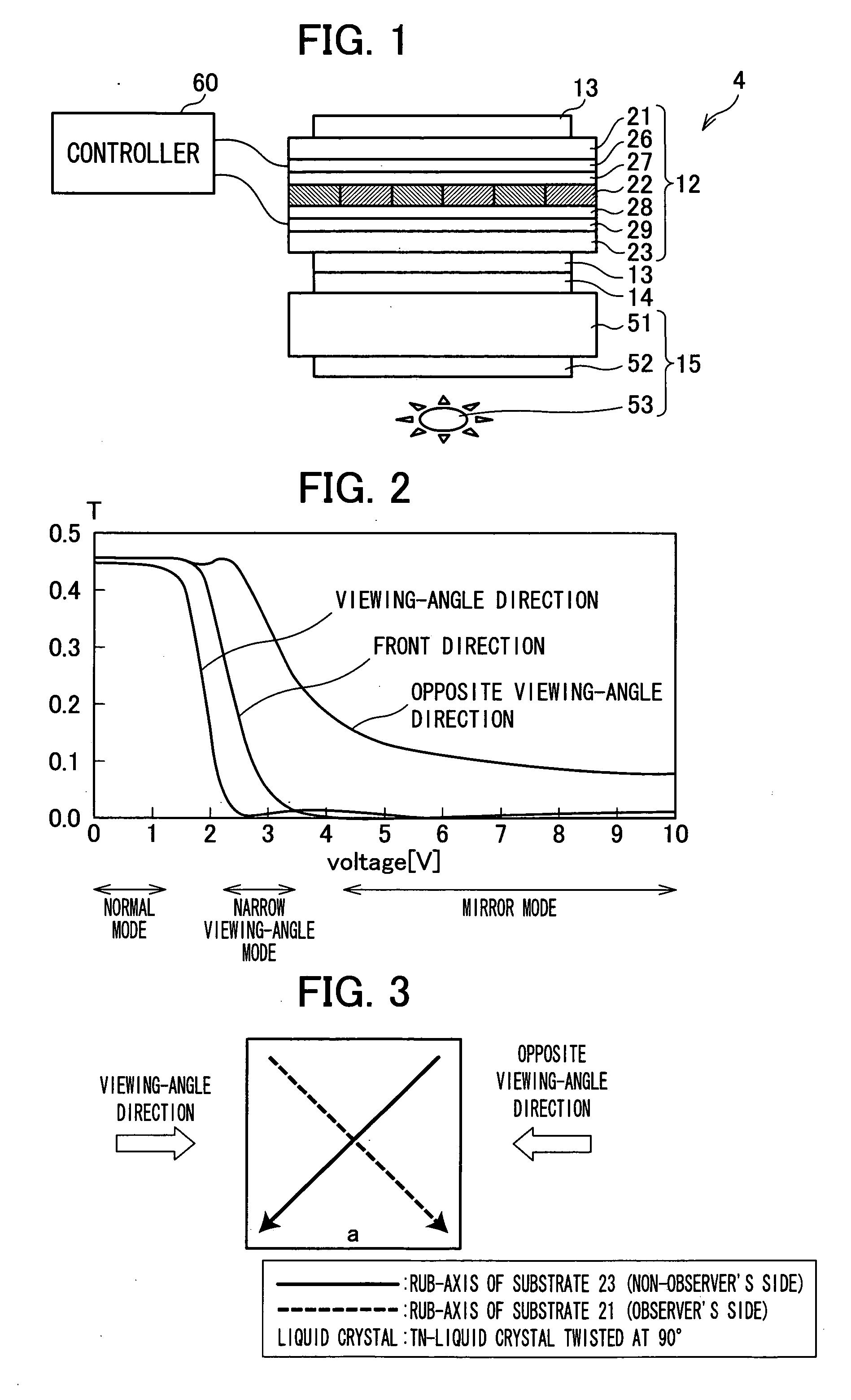
[0011] Another object of the present invention is to realize a display apparatus that, by switching modes, (i) causes a displayed image to be visible from all directions, (ii) makes it difficult to observe a displayed image from a particular direction, and (iii) allows mirror-surface displaying.
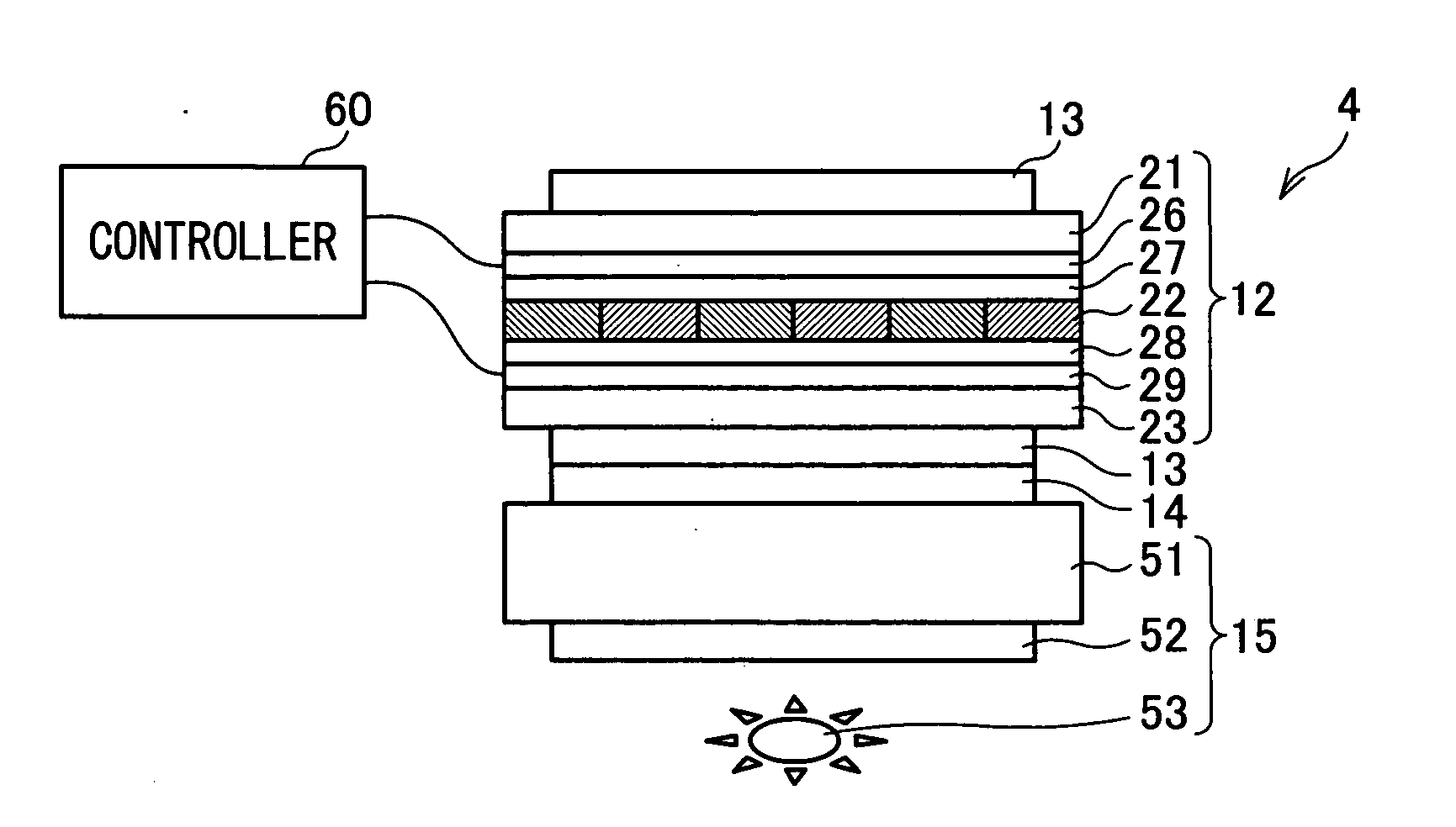
[0016] Further, in the above structure, there are a first polarizer, a display switching section, a reflective polarizer, and a second polarizer on a front face of the picture display section. Accordingly, if all of the members are allowed to transmit light, then the structure becomes the same as the structure that include only the picture display section. This allows the image of the picture display section to become visible from all directions. As such, the wide viewing-angle mode is achieved.
[0019] Note that Patent Document 1 teaches switching the narrow viewing-angle mode and the wide viewing-angle mode, and Patent Document 2 teaches switching the mirror state and the display status. However, neither of the Patent Documents suggests an effect of making it difficult to observe an image by mirror-surface displaying during the narrow viewing-angle mode, which effect has been originally found by the inventors and other persons of the present invention.

Problems solved by technology

However, there arises a problem that confidential documents and information for personal use may be observed by a person nearby.
On the other hand, the narrow viewing-angle mode (i) allows observing a displayed image, in a normal way, from the front of the display where a user is, but (ii) makes it difficult to observe the displayed image from an oblique direction (alternatively, a solid image or a different image is seen).
The structure of Patent Document 1, however, is not adequate for making it difficult to observe a displayed image from an oblique direction (from a side).
The structure of Patent Document 1, therefore, is not adequate for preventing a person from peeking the displayed image from an oblique direction.
No display apparatus that allows switching a viewing-angle control function and a mirror function has been known.

Method used


Image

  • Display apparatus and electronics device
  • Display apparatus and electronics device
  • Display apparatus and electronics device

Examples


embodiment 1

[0040] The following describes an embodiment of the present invention, with reference to FIGS. 1 to 7.

[0041]FIG. 7 illustrates an exterior of a portable phone (electronic device) 1 according to an embodiment of the present invention. The portable phone 1 of the present embodiment is so-called clamshell-type, and is illustrated in the figure in an open state. What illustrated in FIG. 7 is a face of the portable phone 1 that comes inside when the portable phone 1 is folded. A user mainly uses this face when using the portable phone 1 that is in an open state. Accordingly, the face illustrated in FIG. 7 will be referred to as a front face (upper face) in the present application.

[0042] As illustrated in FIG. 7, the portable phone 1 includes a main body 2 and a covering body 3. The main body 2 and the covering body 3 are connected by a hinge. The covering body 3 includes, on a front face side, a display section (display apparatus) 4.

[0043] The main body 2 includes, on a front face sid...

embodiment 2

[0091] The following describes another embodiment of the present invention, with reference to FIGS. 8 to 14. In the following description of the present embodiment, reference will be made, when necessary, to FIGS. 1 to 7, which were used in the description of Embodiment 1. Note that, in the following description, mainly differences between the present embodiment and Embodiment 1 will be described, and description of common points is omitted.

[0092] Embodiment 1 described the portable phone 1 with three modes, the viewing-angle control function (narrow viewing-angle mode and wide viewing-angle mode) and the mirror function (mirror mode). In the present invention, however, the portable phone 1 may function as a portable phone without the mirror mode.

[0093] Thus, in the present embodiment, the portable phone 1 with the viewing-angle control function will be described. The basic structure of the portable phone 1 according to the present embodiment is same as that of the portable phone ...


PUM


Abstract

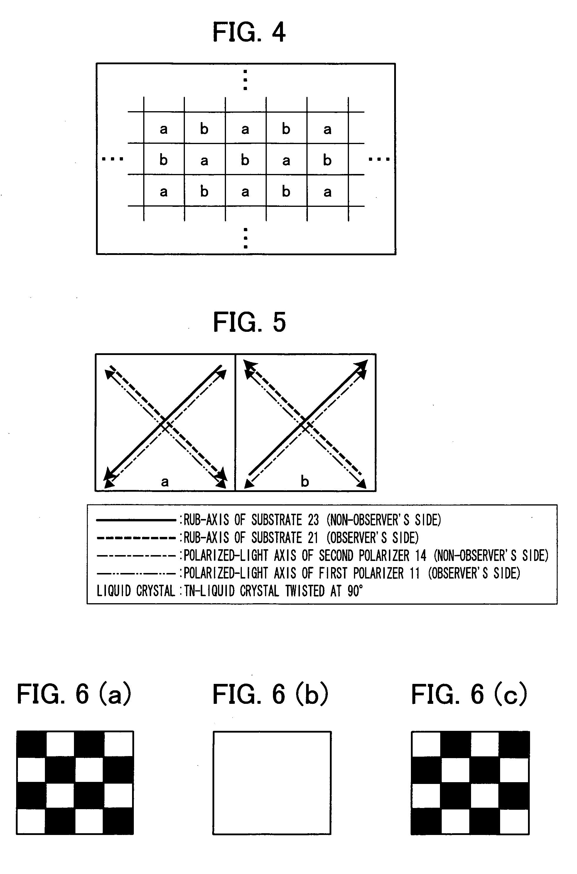
A display section of a portable phone includes a first polarizer, a switching panel section, a reflective polarizer, and a main panel section. The switching panel section has a liquid crystal layer including a plurality of regions having at least two different alignment directions. This makes it possible, by utilizing the difference in the alignment direction of the liquid crystal layer, to make the image difficult to observe by a sight-line from an oblique direction. Furthermore, it is also possible, by utilizing the mirror-surface displaying caused by the reflective polarizer, to make the image significantly difficult to observe.

Description

[0001] This Nonprovisional application claims priority under 35 U.S.C. § 119(a) on Patent Applications No. 285476 / 2005 filed in Japan on Sep. 29, 2005, and No. 008013 / 2006 filed in Japan on Jan. 16, 2006, the entire contents of which are hereby incorporated by reference. FIELD OF THE INVENTION [0002] The present invention relates to a display apparatus and an electronic device including the display apparatus, and particularly, relates to a display apparatus and an electronic device that make it difficult to observe a displayed image from an oblique direction. The present invention also relates to a display apparatus that allows switching a viewing-angle control function and a mirror function, and an electronic device that includes the display apparatus. BACKGROUND OF THE INVENTION [0003] In recent years, electronic devices have become lighter and lighter in weight. This allows carrying and using an electronic device that includes a display, such as a portable phone and a mobile PC, ...

Claims


Application Information

Patent Timeline
IPC IPC(8): G09G3/36
CPCG02F1/1323G02F1/133753G02F1/13471G09G2320/068G09G3/3208G09G3/3611G09G2300/023G09G3/28
Inventor YABUTA, KOJIFUKUSHIMA, HIROSHIIMAI, AKIRATAKATANI, TOMOO
Owner SHARP KK
Learn More