Control method for twin synchronization

a control method and twin synchronization technology, applied in the direction of electric programme control, program control, instruments, etc., can solve the problems of the deviation between the two axes that must arise, and the inability to grasp characteristics such as the distortion of the machine itself. achieve the effect of high speed and highly accurate synchronization control

Active Publication Date: 2007-03-22
YASKAWA DENKI KK
View PDF4 Cites 8 Cited by
  • Summary
  • Abstract
  • Description
  • Claims
  • Application Information

AI Technical Summary

Benefits of technology

[0013] A high speed and highly accurate synchronization control that cannot be realized by a usual control system can be realized by the above described means without receiving an adverse effect due to the rigidity or the distortion of a machine system.
[0020] Thus, a high speed and highly accurate synchronization control that cannot be realized by a usual control system can be realized without receiving an adverse effect due to the rigidity or the distortion of a machine system and the change of the center of gravity due to the movement of the X-axis of the fastening part.

Problems solved by technology

Accordingly, characteristics such as a distortion of a machine itself cannot be grasped.
However, in an actual machine, since there are necessarily an installation error, the attaching error of a position sensor, a distortion and backlash of each axis, the deviation between the two axes necessarily arises depending on positions.
Also at this time, when the two axes are electrically operated at the same time under the speed control and the position control like during the return to the origin operation, the motor of each axis gives a stress to the machine side, so that the characteristics such as the distortion of the machine itself cannot be grasped.

Method used


Image

  • Control method for twin synchronization
  • Control method for twin synchronization
  • Control method for twin synchronization

Examples


first embodiment

[0032] Now, the present invention will be described below by referring to the drawings.

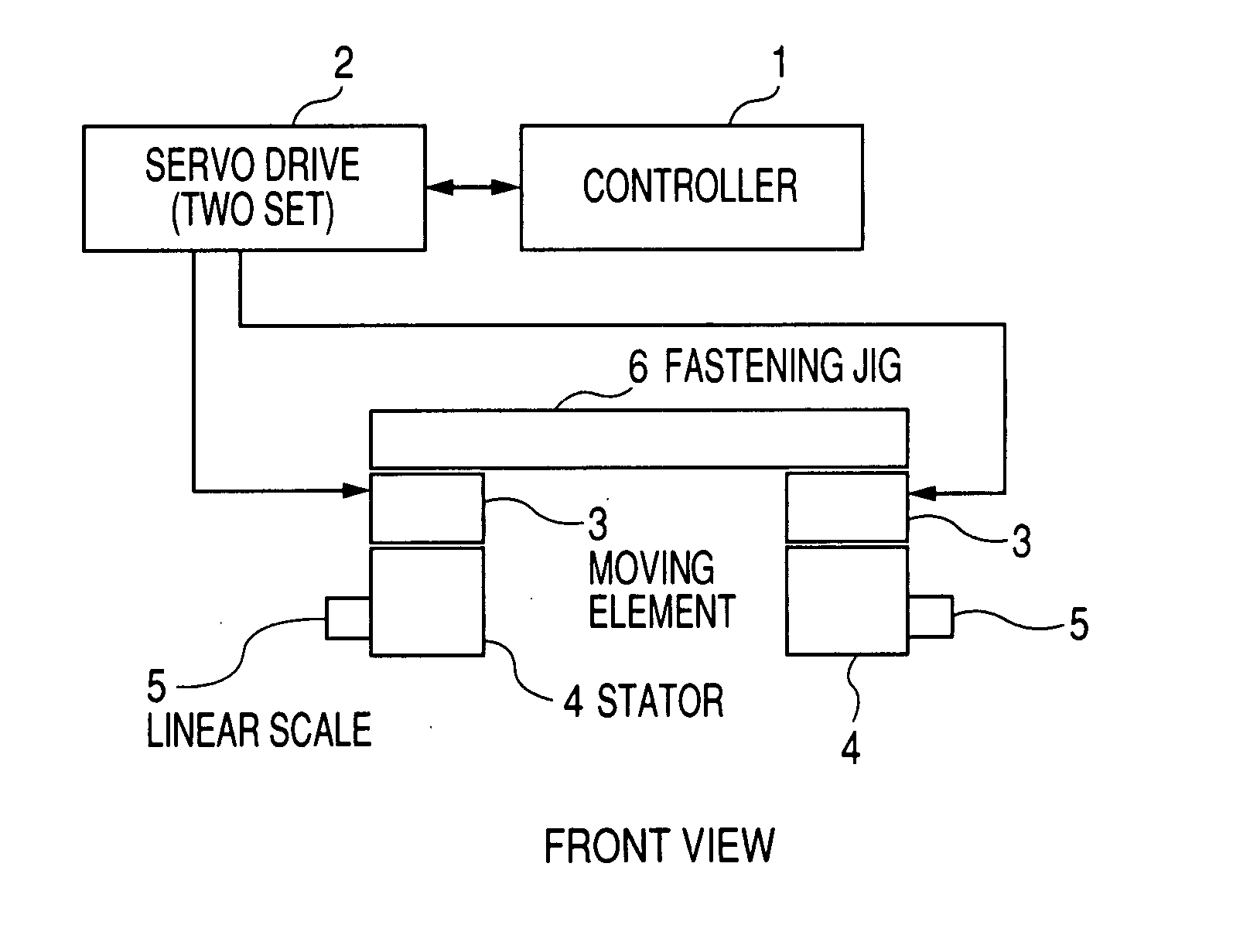
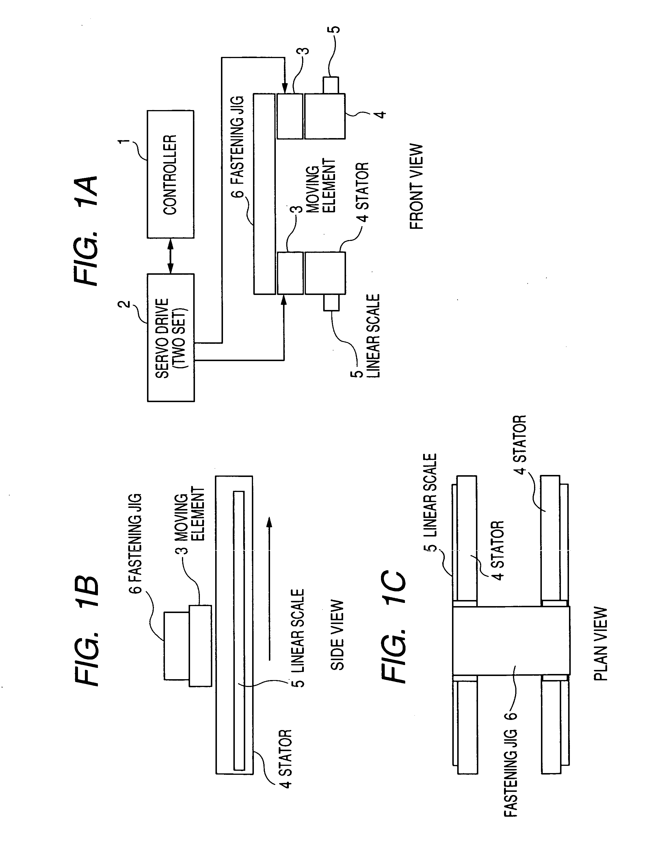
[0033]FIG. 1 shows the structure of a first embodiment of the present invention formed by using a linear motor. FIG. 1(a) is a front view, FIG. 1(b) is a side view and FIG. 1(c) is a plan view. In the drawing, reference numeral 1 designates a controller, 2 designates a servo drive, 3 designates a moving element, 4 designates a stator, 5 designates a linear scale and 6 designates a fastening jig for mechanically fastening two axes together.

[0034]FIG. 2 is a control block diagram of this embodiment. In FIG. 2, the controller 1 includes the main position command generating part 11, the interpolating part 12, the phase lead compensating part 13, the function part 14 for generating a torsion part corrected value, the differential operating parts 15 and 16, the scale converting part 17 and the gain amplifier 18. Further, the servo drives 2-1 and 2-2 include the position loop control parts 21, the speed...

second embodiment

[0047] Now, the present invention will be described below.

[0048]FIG. 7 is a block diagram of a controller showing a second embodiment of the present invention.

[0049] In FIG. 7, the controller 1 includes a main position command generating part 31, an interpolating part 32, differential operating parts 33 and 34, inertia calculating parts 35 and 37, a y1-axis torque FF (feed forward) compensating part 36, a y2-axis torque FF compensating part 38, an X-axis position detecting part 39, a function part 40 for generating an inertia compensating gain and inertia compensating parts 41 and 42.

[0050] In the second embodiment, an inertia correction when an X-axis moves is controlled by a torque FF (feed forward) compensation.

[0051] In a twin synchronization type (a gantry type) machine, when a fastening jig part 6 (X-axis) moves and twin driving parts (Y1 and Y2 axes) are synchronously operated, the position of a center of gravity moves. Thus, synchronization accuracy is deteriorated.

[0052...


PUM


Abstract

It is an object of the present invention to provide a twin synchronization method that can easily realize a high speed and highly accurate operation for a machine having a gantry type structure. According to the present invention, in a control method for a twin synchronization in which two motors for driving two axes (moving elements 3) mechanically fastened to each other by a fastening part (a fastening jig 6) are synchronously operated, one of the two axes is operated at low speed by a position control and the other axis is allowed to freely run and follow the one axis and a return to the origin is performed. A positional deviation between the one axis and the other axis is measured at an arbitrary pitch. The positional deviation corresponding to a position where the one axis travels is stored in a data base as a function. One position command is directly distributed to the one axis as a main position command and the position command is distributed to the other axis as a position command corrected by using the function stored in the data base to perform an operation.

Description

TECHNICAL FIELD [0001] The present invention relates to an applied machine applied to a high speed positioning control for gantry type machines such as a high speed conveying machine or other machines, and more particularly to a control method for high speed and highly accurate uses. RELATED ART [0002] In recent years, in the high speed and highly accurate conveying machine of an industrial machine field, what is called a gantry type machine in which two axes are synchronously operated has been introduced. When a synchronization between the axes is carried out in the gantry type machine, a high speed and highly accurate synchronous operation is hardly realized in a machine low in its rigidity and having torsion or backlash. [0003] Usually, to reduce a deviation between the two axes, a method has been employed in which the same position command and the speed command are respectively distributed to the axes from a controller to adjust the gain of a position controlling and speed contr...

Claims


Application Information

Patent Timeline
Patent Type & Authority Applications(United States)
IPC IPC(8): G06F19/00G05D3/12G05D3/00H02P5/46H02P5/48
CPCH02P5/483H02P5/485H02P5/46
Inventor WATANABE, KANJIWATARIYOU, KAZUHIKOKIYOTA, NAOTO
Owner YASKAWA DENKI KK
Why Eureka
Try Eureka