Light emitting device

a light-emitting device and light-emitting technology, which is applied in the direction of semiconductor devices, active medium materials, laser details, etc., can solve the problems of large energy, easy re-absorption of light emitted by the light-emitting device, and large energy of the light-emitting device, so as to improve the conversion efficiency and facilitate the re-emission. , the effect of increasing the amount of the conversion process

Active Publication Date: 2007-03-22
EPISTAR CORP
View PDF3 Cites 12 Cited by
  • Summary
  • Abstract
  • Description
  • Claims
  • Application Information

AI Technical Summary

Benefits of technology

[0063] According to the above-described light emitting device 100 of the first embodiment, the light emitting conversion unit 70 is configured by the first region 20a, the second region 30a, and the wavelength selecting material 40 between the first region 20a and second region 30a. The first region 20a includes the green light emitting color conversion martial 20G and the red light emitting color conversion material 20R. In addition, the second region 30a includes the blue light emitting conversion material 30.
[0064] By disposing the blue light emitting color conversion material 30 in the second region 30a in this manner, the blue light emitted from the blue light emitting color conversion material 30 is allowed to be easily emitted to the outside of the light emitting conversion unit 70 without being absorbed by the green light emitting color conversion material 20G and the red light emitting color conversion material 20R. That is, an increase in amount of a conversion process that the blue light emitted from the blue light emitting conversion material 30 is absorbed again by the green light emitting conversion material 20G and the red light emitting color conversion material 20R to be converted to green and red light, respectively, can be reduced
[0065] In addition, the blue light emitted from the blue light emitting color conversion material 30 is reflected by the wavelength selecting material 40 and is then emitted from the opposite side of the wavelength selecting material 40 in the second region 30

Problems solved by technology

However, since the above-described light emitting device 104 disperses the color conversion materials in the transparent resin 54, there is a problem in that light emitted by the color conversion materials may be absorbed again as excitation light of different color conversion materials.
As a result, there is a problem in that conversion ef

Method used


Image

  • Light emitting device
  • Light emitting device
  • Light emitting device

Examples


first embodiment

[Modification of First Embodiment]

[0067] A modification of the light emitting device 100 according to the first embodiment will be described below by referring to FIGS. 6 and 7. It is to be noted that with regard to the modified embodiments shown in FIGS. 6 and 7 differences between the light emitting device 100 according to the above-described first embodiment and the modification thereof will be mainly described.

[0068] In a light emitting device 101 shown in FIG. 6, a light emitting conversion unit 71 does not include a wavelength selecting material 40, and is configured by a first region 21a and a second region 31a. In addition, as for color conversion materials, different from the three kinds of color conversion materials of the light emitting device 100, two kinds of color conversion materials of a red light emitting color conversion material 21 and a yellow light emitting color conversion material 31 are used.

[0069] Specifically, in a case where white light is emitted from t...

second embodiment

[Second Embodiment]

(Light Emitting Device)

[0084] A light emitting device 103 according to a second embodiment of the present invention will be described below by referring to FIG. 8. FIG. 8 is a cross sectional view showing a light emitting device 103 (white LED) according to the second embodiment, which emits white light.

[0085] It is to be noted that with regard to the light emitting device 103 according to the second embodiment, differences with the above-described light emitting device 100 according to the first embodiment will be mainly described.

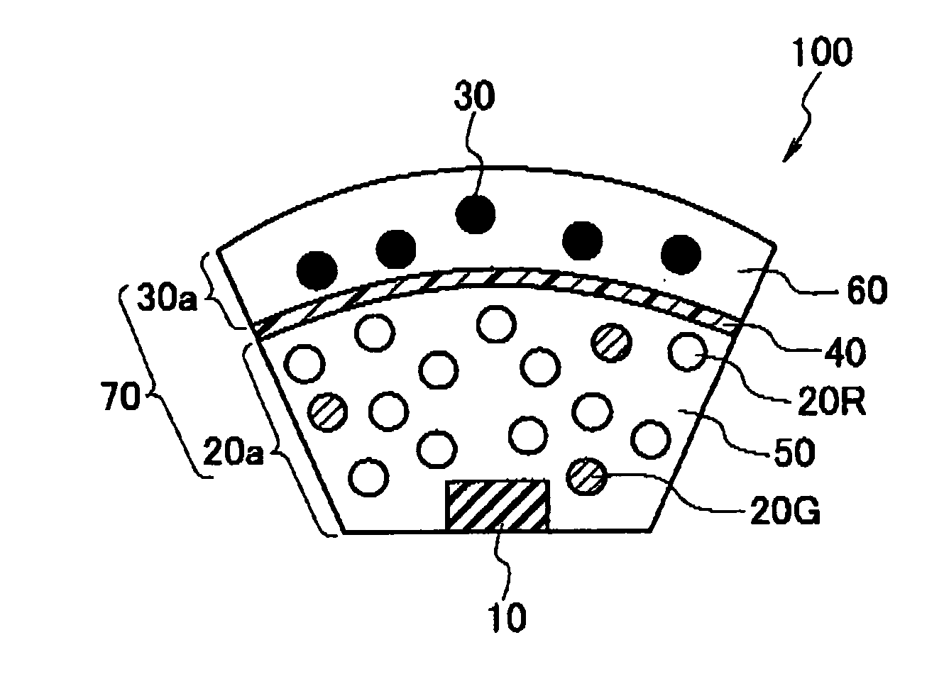
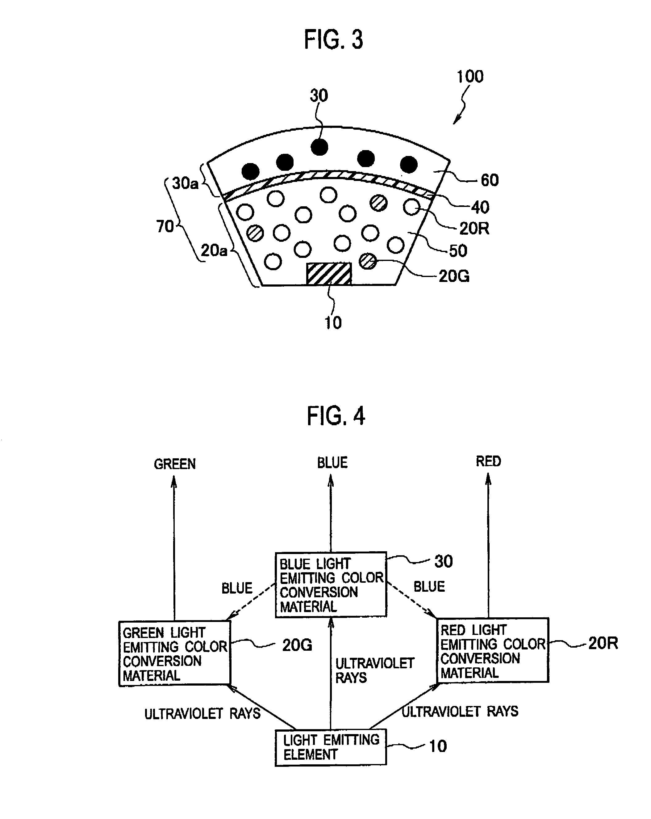
[0086] In the light emitting device 100 according to the first embodiment, as shown in FIG. 3, the light emitting conversion unit 70 is configured by the first region 20a, the wavelength selecting material 40, and the second region 30a.

[0087] In contrast, the light emitting device 103 according to the second embodiment is, as shown in FIG. 8, configured by a cup portion 200, a condenser lens 201 covering the upper portion of the cu...

example 1

[0103] In Example 1, as shown in FIG. 3, a light emitting device in which a light emitting element, a first region including a green light emitting color conversion material and a red light emitting color conversion material, a wavelength selecting material, and a second region including a blue light emitting color conversion material are provided is manufactured. Here, a GaN-based material is used for the light emitting element, and a peak of a light emitting wavelength is between 380 and 420 nm.

[0104] Firstly, processing of manufacturing the green and the red light emitting color conversion materials is carried out Here, as shown in FIG. 3, the first region including the green light emitting color conversion material and the red light emitting color conversion material is formed. The green light emitting color conversion material and the red light emitting color conversion material used here were materials of oxidant system, and light to be emitted had peaks at the vicinity of 53...


PUM


Abstract

A light emitting device includes a light emitting element which emits light with a first wavelength; and a light emitting conversion unit for converting the light with the first wavelength by using wavelength conversion materials including a short wavelength conversion material and a long wavelength conversion material, the short wavelength conversion material being that which emits light with a second wavelength longer in wavelength than the light with the first wavelength, by absorbing the light with the first wavelength, and the long wavelength conversion material being that which emits light with a wavelength longer than the second wavelength by absorbing the light with the first wavelength. A proportion of the short wavelength conversion material of the wavelength conversion materials included in a first region is smaller than that of the short wavelength conversion material of the wavelength conversion materials included in the entire light emitting conversion unit, and a proportion of the short wavelength conversion material of the wavelength conversion materials included in a second region is larger than that of the short wavelength conversion material of the wavelength conversion materials included in the entire light emitting conversion unit.

Description

CROSS REFERENCE TO RELATED APPLICATION [0001] This application is based upon and claims the benefit of priority from prior Japanese Patent Application P2005-276056 filed on Sep.22, 2005; the entire contents of which are incorporated by reference herein. BACKGROUND OF THE INVENTION [0002] 1. Field of the Invention [0003] The present invention relates to a light emitting device. [0004] 2. Description of the Related Art [0005] Conventionally, light emitting devices using a technology that converts a light wavelength irradiated from a light emitting diode (LED) chip by a color conversion material have been developed. Among such light emitting devices, since a white LED is expected to be used for lighting, it is required for a while LED to have high-color rendering properties. Here, the high-color rendering properties refer to a property having a light emitting spectrum near sunlight. As the color rendering properties increase, the state of a color of an object becomes closer to a state ...

Claims


Application Information

Patent Timeline
IPC IPC(8): H01S3/10H01L33/32H01L33/50H01L33/54H01L33/56H01L33/60H01L33/62
CPCH01L33/504H01L33/44
Inventor TOKUNAGA, SEIICHI
Owner EPISTAR CORP
Why Eureka
Try Eureka