
Cargo handler for vehicles with rear cargo space

a rear cargo and cargo handler technology, applied in the field of platform trucks, can solve the problems of limited lifting capacity, high cost of buying and maintaining type prior art cargo handlers, and high cost of second type prior art cargo handlers, and design for only limited applications

Inactive Publication Date: 2007-03-15
KIM DAE S
View PDF12 Cites 7 Cited by
  • Summary
  • Abstract
  • Description
  • Claims
  • Application Information

AI Technical Summary

Benefits of technology

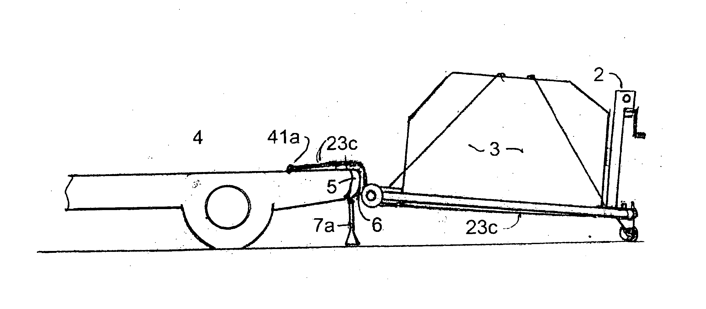
[0009] This invention provides an efficient means for loading a cargo on a pallet / platform, putting the loaded platform into a flat rear cargo space of a van, mini-van, station wagon, SUV, small truck with a removable rear gate or truck, securing the cargo in transit without damage to the floor, unloading the platform off the vehicle at the destination, moving the loaded platform on the ground and unloading the cargo off the platform.
[0010] This invention makes every vehicle with a flat rear cargo space a safe and energy efficient cargo carrier for small businesses and do-it-yourselfers. As more than half of all new passenger vehicles have a large rear cargo space, their newly expanded use should bring enormous saving in energy, time and money with this complete cargo handler.
[0014] In this invention, the third belt is also adjustably connected to the middle of the shaft. The winding direction of the middle belt can be either opposite or the same of that of the pair. The pair of belts slides under and supports the smooth bottom side of the platform and firmly tied to the floor of cargo space for lifting the front end of the platform but the middle belt is routed to the topside and can go either direction, forward for pulling a cargo onto the platform by tying it to the cargo or backward for pulling the loaded platform off the vehicle by tying its free end to a fixed object on the ground. An additional means of adjusting its length keeps the belts tight for a safe unloading.
[0015] To pull the cargo onto the platform with the middle belt, the front casters are removed and the back end of the cargo is lifted onto the front end of the platform. When the rear part of the cargo reaches the column(s), the cargo is anchored down on platform against the column(s) with a rope or a belt. For unloading the cargo, the front casters are replaced with a pair of thin strips of wood to keep the belts off the ground and the free ends of the pair of belts are tied around the rear of the cargo to pull it forward off the platform. The inclined platform allows gravity to help in pushing the cargo off. To lift one end of the cargo or the front end of the platform for removing or re-mounting the wheels on the ground, a tire iron or a similar lever and a pivoting block are used.
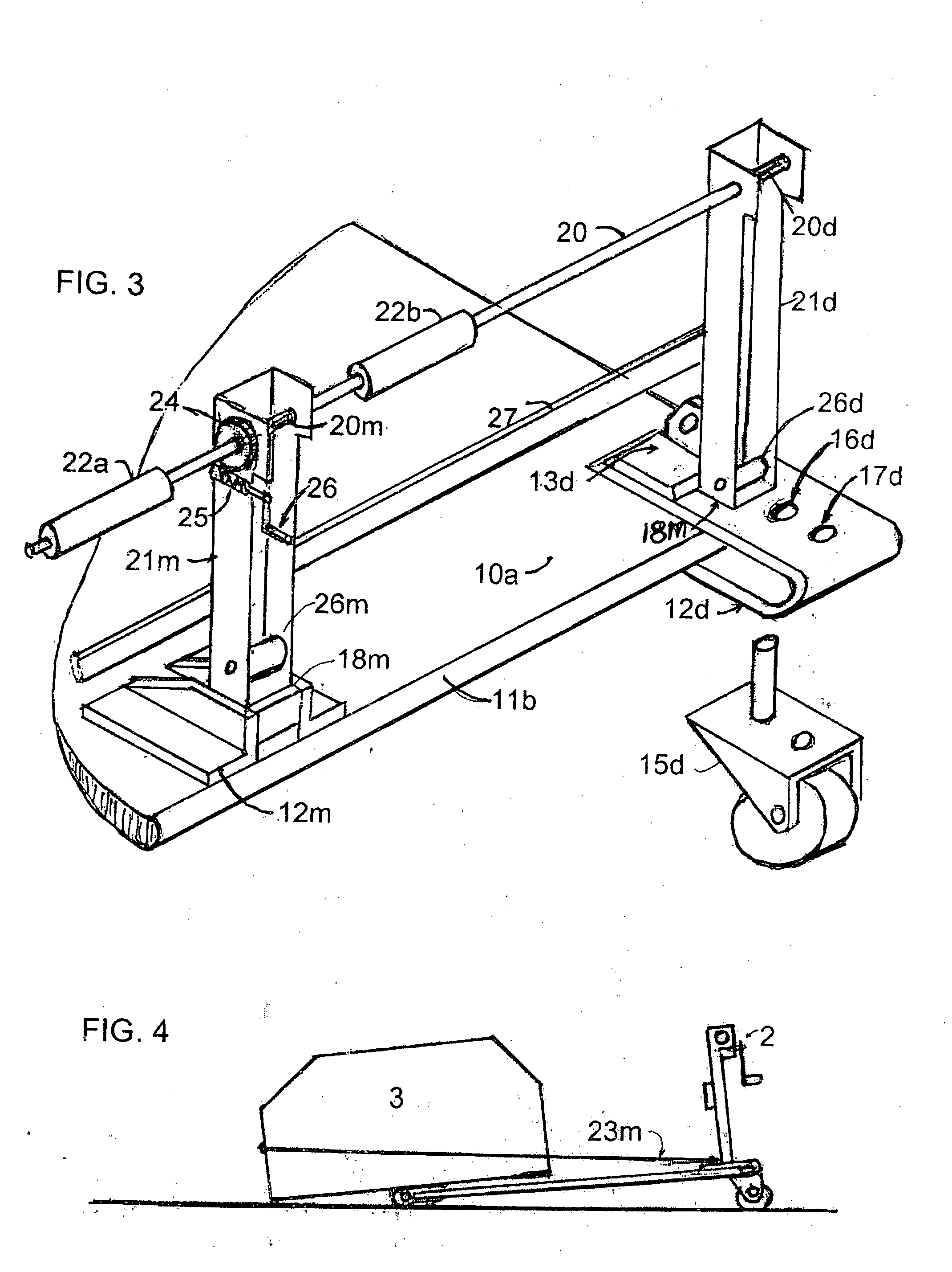
[0017] Although the maximum height of the columns is limited by the rear door opening of the cargo space, the shaft is high enough to be a comfortable handle bar for the platform trucking. Four U-shaped smooth metal plates cover and re-enforce the corners to provide bases for anchors and casters. The front pair protrudes to clear the usually bowing mid-part of rear bumper while lifting and holds the cantilever axles of fixed front wheels for more clearance. The rear pair provides bases for the outer columns and a sufficient distance between the columns and rear casters to prevent the loaded platform from flipping before the tipping. For an added safety, the casters are locked in their rear most position. For compact storage, the columns and winch system are made removable.

Problems solved by technology

Sometimes, large trucks carry a pallet truck that has only limited lifting capability for moving or re-arranging cargo within the truck.
The first type prior art cargo-handling devices are industrial in nature and expensive to buy and maintain.
The second type prior art devices are also costly and designed for only limited application.
Neither type of devices are suitable for general use by the general public or small business owners who own extremely popular vans, mini-vans, station wagons, SUVs or small trucks.

Method used


Image

  • Cargo handler for vehicles with rear cargo space
  • Cargo handler for vehicles with rear cargo space
  • Cargo handler for vehicles with rear cargo space

Examples


Embodiment Construction

[0029] In FIG. 1 and details inFIG. 2 and 3, a ¾″ thick rectangular plywood platform 1 has smooth but tough top 10a and bottom 10b surfaces and rounded front end 11a and rear end 11b for easy sliding. Its four corners are re-enforced and covered by 3 / 16″ thick, 4″ wide U-shaped metal plates 12a, 12b, 12c and 12d with cargo holding anchors 13a, 13b, 13c and 13d. The front plates 12a and 12b hold cantilever axles 14a and 14b with retainer-pin holes 19a and 19b (not shown) near the end for removable wheels 15a and 15b. Also the rear plates 12c and 12d have square openings 18c and 18d for holding the outer columns 21c and 21d of three-post winch system 2, holes 16c and 16d for holding the mounting shafts of removable swiveling casters 15c and 15d and holes 17c and 17d for removable pins which hold the casters at their rear most positions for safety while the front end 11a is lifted. Each plate and anchor are attached to the platform with a set of four 5 / 16″ counter sunken flat head scre...


PUM


Abstract

An efficient means for loading a heavy cargo on a pallet / platform, putting the loaded platform into a flat rear cargo space of a van, mini-van, station wagon, SUV, or truck, securing the cargo in transit while protecting the floor, unloading the platform from the vehicle at the destination, moving the loaded platform on the ground and unloading the cargo off the platform uses a three-belt winch system. A matched pair is used to load and unload the loaded platform with removable casters by lifting its front end over the rear bumper, tipping to level and sliding into the securing position for traveling. The third belt is used to unload the platform and load the cargo onto the platform.

Description

BACKGROUND OF THE INVENTION [0001] 1. Field of the Invention [0002] This invention relates to a device and method for loading a cargo into a vehicle with a flat rear cargo space, securing the cargo while transporting, unloading the cargo at the destination and moving the cargo on the ground. [0003] More specifically, this invention relates to a platform truck that converts into a pallet that loads, unloads and secures a heavy cargo into any flat rear cargo space of a van, mini van, station wagon, SUV, small truck with a removable rear gate or truck. [0004] 2. Descriptions of the Prior Arts [0005] Prior art cargo handlers can be grouped into two general types. One is a distinct and separate wheeled or tracked vehicle with means of lifting / lowering a cargo and the other type is a device attached to or / and carried on a vehicle. [0006] The first type includes large container handling systems, forklift trucks, small hand pallet lift trucks and mobile conveyor belts. Among them, forklift ...

Claims


Application Information

Patent Timeline
IPC IPC(8): B60P9/00
CPCB60P1/6427B60P1/003
Inventor KIM, DAE S.
Owner KIM DAE S
Learn More