
High speed transmission system

Active Publication Date: 2007-03-15
ANALOG DEVICES INC
View PDF15 Cites 18 Cited by
  • Summary
  • Abstract
  • Description
  • Claims
  • Application Information

AI Technical Summary

Benefits of technology

[0007] It is a further object of this invention to provide the improved high speed transmission system which avoids skewing problems between clock and data occurring in traditional serial ADC systems.
[0008] It is a further object of this invention to provide the improved high speed transmission system which obviates the need to adjust the clock to the data.
[0009] It is a further object of this invention to provide the improved high speed transmission system which enables use of more robust, real time error detecting and error correcting.
[0010] It is a further object of this invention to provide the improved high speed transmission system which provides flexibility to trade off marker size including header and / or error bits to obtain efficiency of over 87%.
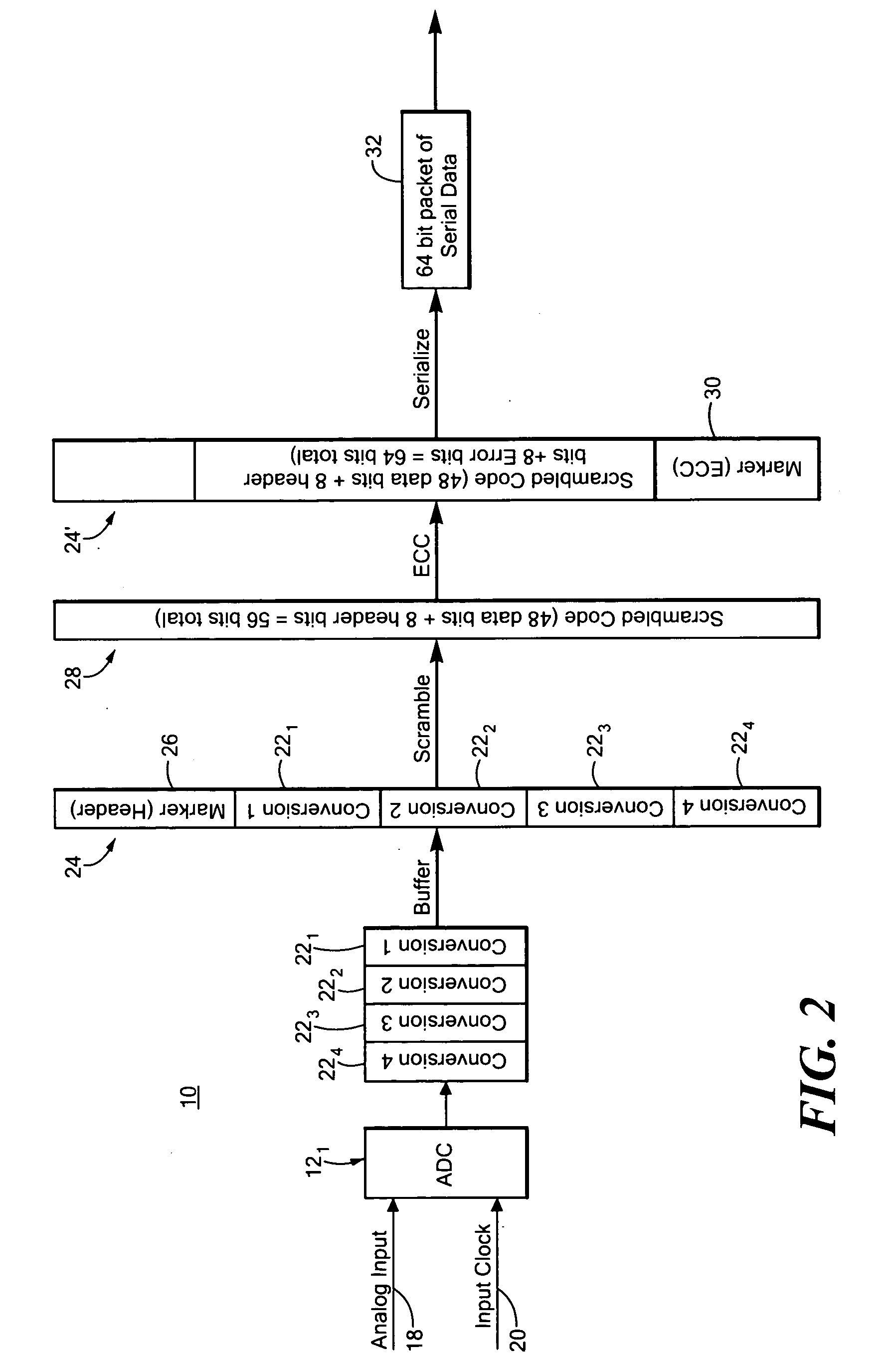
[0011] The invention results from the realization that an improved, more efficient, high speed transmission system which eliminates the need for additional clocks and clock pins, avoids skewing problems between clock and data signals and makes use of more robust, real time, error checking / correcting can be effected by assembling a number of sample conversion words into a data packet with a marker word which can be a header or error word or both and by serializing the data packet with an embedded clock for transmission.

Problems solved by technology

Parallel mode is the simplest to implement but it demands the most interconnect lines, which requires more space and complex routing, and often more power.
However, serial data transmission does require more speed per data line and can be much more complex to implement than parallel transmission.
Higher output pin numbers makes routing to the receiver more complex.
And it is cumbersome to make the clock edges adjustable so they can be properly aligned in unambiguous regions of the data in all channels.
Further, the error checking is not sufficiently robust to correct the errors and does not detect the errors in real time.

Method used


Image

  • High speed transmission system
  • High speed transmission system
  • High speed transmission system

Examples


Embodiment Construction

[0024] Aside from the preferred embodiment or embodiments disclosed below, this invention is capable of other embodiments and of being practiced or being carried out in various ways. Thus, it is to be understood that the invention is not limited in its application to the details of construction and the arrangements of components set forth in the following description or illustrated in the drawings. If only one embodiment is described herein, the claims hereof are not to be limited to that embodiment. Moreover, the claims hereof are not to be read restrictively unless there is clear and convincing evidence manifesting a certain exclusion, restriction, or disclaimer.

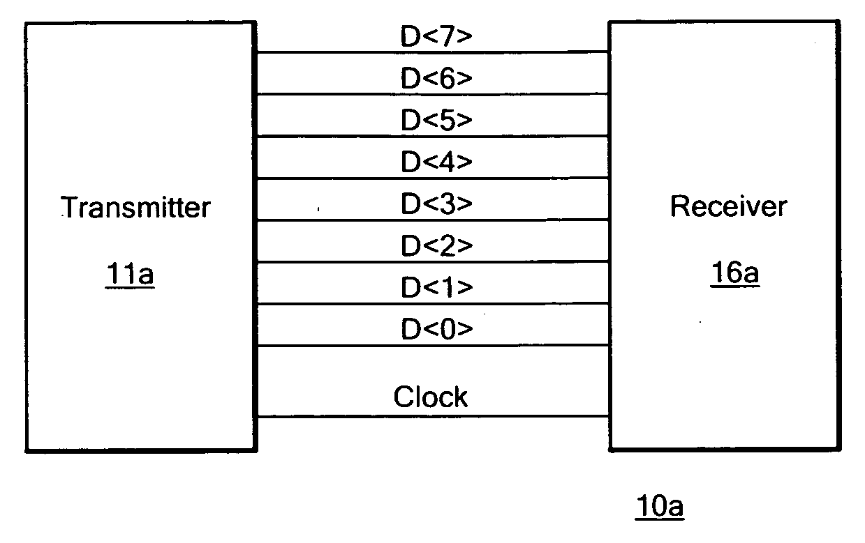
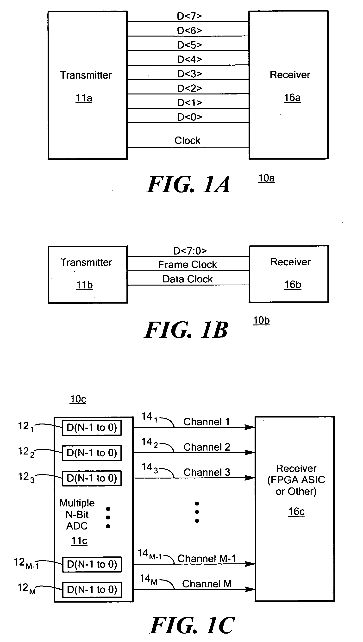
[0025]FIG. 1A shows a full parallel 8-bit digital data transmission system 10a between a transmitter 11a and receiver 16a. Note that eight data lines and a clock are required to move the data from the transmitter 11a to the receiver 16a. FIG. 1B on the other hand shows an 8-bit digital data transmission system 10b impleme...


PUM


Abstract

A high speed transmission system includes at least one transmitter; a buffer circuit for assembling into a data packet in parallel a number of sample conversion words from said transmitter; a marker circuit for adding a marker word to said data packet for framing said data packet; and a serializer circuit for serializing said data packet either before or after said marker word is added, with an embedded clock for transmission.

Description

RELATED APPLICATIONS [0001] This application claims benefit of U.S. Provisional Application Ser. No. 60 / 717,312 filed Sep. 15, 2005 incorporated by reference herein.FIELD OF THE INVENTION [0002] This invention relates to a high speed, transmission system and more particularly, in one implementation to a high speed analog to digital converter (ADC) system. BACKGROUND OF THE INVENTION [0003] Digital data transmission can be done either in parallel mode, serial mode, or a combination of the two. Parallel mode is the simplest to implement but it demands the most interconnect lines, which requires more space and complex routing, and often more power. Serial transmission requires only a single data line which implies less space and simplified routing, and it usually comes with a power savings. However, serial data transmission does require more speed per data line and can be much more complex to implement than parallel transmission. Analog to digital converters (ADCs) traditionally provid...

Claims


Application Information

Patent Timeline
IPC IPC(8): H03M1/12
CPCG01R31/31716H04L1/0083H04L7/041H04L49/9094H04L49/90H04L49/901H04L7/048
Inventor JARMAN, DAVID C.VASSALLI, LUCA
Owner ANALOG DEVICES INC
Learn More