
Wind turbine load control method

Inactive Publication Date: 2007-03-15
MCNERNEY GERALD
View PDF2 Cites 112 Cited by
  • Summary
  • Abstract
  • Description
  • Claims
  • Application Information

AI Technical Summary

Benefits of technology

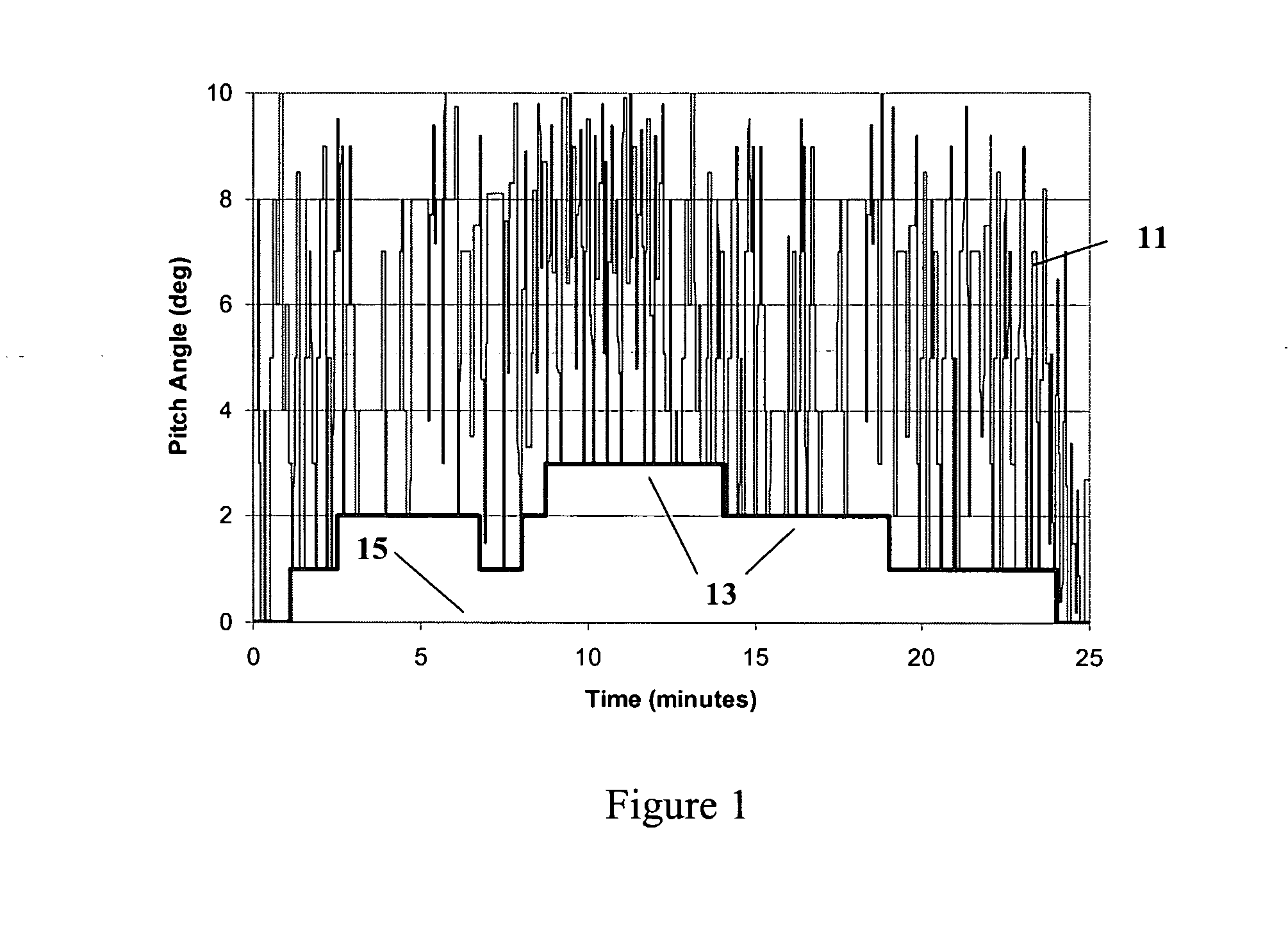
[0013] The operating loads of a wind turbine with a pitch control system having sufficient capability can be significantly reduced by the use of a simple control algorithm and load sensor. The method works by increasing the minimum pitch angle parameter of the controller for extended periods of time while allowing the controller to vary the pitch angle normally as the turbine loads increase in high or gusty wind conditions, or in conditions of high wind shear. In other words, based on load measurements, the load limiting algorithm adjusts a minimum pitch angle parameter to prevent the dynamic control algorithm from lowering the pitch angle to values that will cause high loads. This requires the controller to have measurements or dynamic estimates of wind speeds or loads, and sufficient flexibility to use the measured data to adjust the minimum pitch angle parameter. The controller will allow the minimum pitch angle parameter to relax back toward the absolute minimum pitch angle when the loads diminish for a sufficiently long period of time. If this approach causes the average power of the turbine to decrease below rated power in wind speeds above the wind speed of rated power, the rated power set point can be adjusted upward to compensate.
[0014] This invention will decrease loads and allow the turbine to operate in higher winds and / or with a larger rotor in most wind sites. These changes will result in significantly higher energy capture while only incurring marginally higher costs of an additional sensor and longer blades. Consequently, the cost of energy, the ultimate economic measure of a wind turbine, will be lower, making wind energy an attractive source of fuel displacement and power capacity.

Problems solved by technology

These changes will result in significantly higher energy capture while only incurring marginally higher costs of an additional sensor and longer blades.

Method used


Image

  • Wind turbine load control method
  • Wind turbine load control method
  • Wind turbine load control method

Examples


second embodiment

[0029] the invention uses average wind speed from direct wind speed measurements or from wind speed estimated by using the power and the pitch angle to vary the minimum pitch angle parameter at or above the absolute minimum pitch angle to reduce loads. FIG. 6 illustrates how the minimum pitch angle parameter will vary with the average wind speed. In this figure, the horizontal axis is the average wind speed, and the vertical axis is the minimum pitch angle parameter axis, with the absolute minimum pitch angle shown. The minimum pitch angle parameter 83 is defined between the cut-in wind speed, Vcut-in the speed at which the winds are strong enough to first generate power, and the high wind cut-out speed, Vcut-out. The minimum pitch angle parameter 83 should increase to limit loads between the rated wind speed, Vrated, and Vcut-out. The minimum pitch angle parameter 83 is shown to increase linearly with average wind speed in FIG. 6, but in practice does not need to increase linearly....


PUM


Abstract

A method for limiting loads in a wind turbine by using measured loads or wind speed to increase the minimum pitch angle for extended periods. The minimum pitch angle will be allowed to relax down to the default when load excursions diminish. The method will allow turbines to capture more energy by operating in higher wind speeds and / or utilizing larger rotors without additional loss of fatigue life.

Description

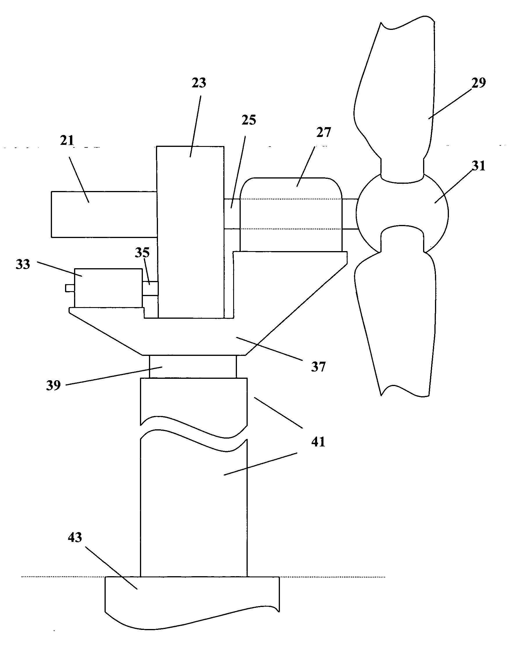
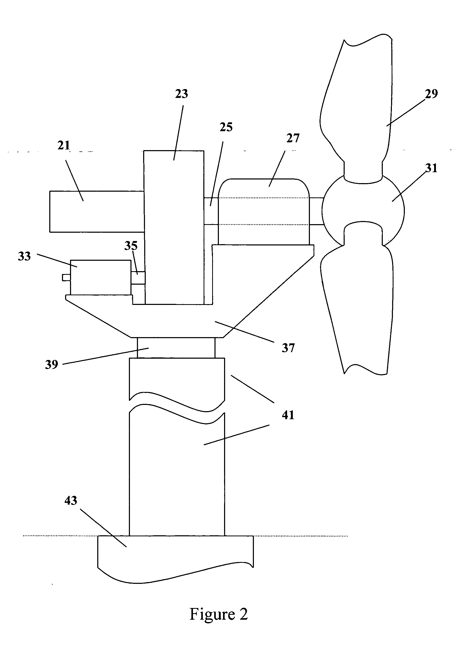
1. FIELD OF THE INVENTION [0001] The present invention is a method by which the control system can be used to limit the operating loads of a wind turbine thereby allowing more energy to be captured. 2. BACKGROUND OF THE INVENTION [0002] A wind turbine is an electric power generating device that captures the energy in the wind by using rotating airfoil blades to develop aerodynamic lift, thereby removing momentum from the air flow and converting it into useful mechanical work. Wind turbines can operate as either horizontal or vertical axis devices, although horizontal axis wind turbines are far more common. [0003] The aerodynamic blades are attached to a hub, which is in turn connected to a main shaft. The main shaft is supported by a main shaft bearing housing assembly which rests on a structural frame. The speed of the main shaft is normally too slow for most generating devices, and so must be increased by transmission, although some modern wind turbines use direct drive generators...

Claims


Application Information

Patent Timeline
IPC IPC(8): F03D9/00H02P9/04
CPCF03D7/0224F03D7/0292F03D7/042Y02E10/723F05B2270/331F05B2270/335F05B2270/32Y02E10/72
Inventor MCNERNEY, GERALD
Owner MCNERNEY GERALD
Learn More